a-Si TFT LCD Single Chip Driver
240RGBx320 Resolution and 262K color
ILI9325
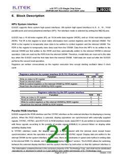
selected for the kind of picture to be displayed on the screen (still and/or moving picture(s)). The RGB
interface, by writing all display data to the internal RAM, allows for transferring data only when updating the
frames of a moving picture, contributing to low power requirement for moving picture display.
Bit Operation
The ILI9325 supports a write data mask function for selectively writing data to the internal RAM in units of bits
and a logical/compare operation to write data to the GRAM only when a condition is met as a result of
comparing the data and the compare register bits. For details, see “Graphics Operation Functions”.
Address Counter (AC)
The address counter (AC) gives an address to the internal GRAM. When the index of the register for setting a
RAM address in the AC is written to the IR, the address information is sent from the IR to the AC. As writing
data to the internal GRAM, the address in the AC is automatically updated plus or minus 1. The window
address function enables writing data only in the rectangular area arbitrarily set by users on the GRAM.
Graphics RAM (GRAM)
GRAM is graphics RAM storing bit-pattern data of 172,820 (240 x 320x 18/8) bytes with 18 bits per pixel.
Grayscale Voltage Generating Circuit
The grayscale voltage generating circuit generates a liquid crystal drive voltage according to grayscale data
set in the γ-correction register to display in 262,144 colors. For details, see the “γ-Correction Register”
section.
Timing Controller
The timing generator generates a timing signal for operation of internal circuits such as the internal GRAM.
The timing for the display operation such as RAM read operation and the timing for the internal operation such
as access from the MPU are generated in the way not to interfere each other.
Oscillator (OSC)
ILI9325 generates RC oscillation with an internal oscillation resistor. The frame rate is adjusted by the register
setting.
LCD Driver Circuit
The LCD driver circuit of ILI9325 consists of a 720-output source driver (S1 ~ S720) and a 320-output gate
driver (G1~G320). Display pattern data are latched when the 720th bit data are input. The latched data control
the source driver and generate a drive waveform. The gate driver for scanning gate lines outputs either VGH
or VGL level. The shift direction of 720 source outputs from the source driver is set with the SS bit and the
shift direction of gate outputs from the gate driver is set with the GS bit. The scan mode by the gate driver is
The information contained herein is the exclusive property of ILI Technology Corp. and shall not be distributed,
reproduced, or disclosed in whole or in part without prior written permission of ILI Technology Corp.
Page 22 of 111
Version: 0.35

 ETC [ ETC ]