a-Si TFT LCD Single Chip Driver
240RGBx320 Resolution and 262K color
ILI9325
6. Block Description
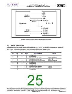
MPU System Interface
ILI9325 supports three system high-speed interfaces: i80-system high-speed interfaces to 8-, 9-, 16-, 18-bit
parallel ports and serial peripheral interface (SPI). The interface mode is selected by setting the IM[3:0] pins.
ILI9325 has a 16-bit index register (IR), an 18-bit write-data register (WDR), and an 18-bit read-data register
(RDR). The IR is the register to store index information from control registers and the internal GRAM. The
WDR is the register to temporarily store data to be written to control registers and the internal GRAM. The
RDR is the register to temporarily store data read from the GRAM. Data from the MPU to be written to the
internal GRAM are first written to the WDR and then automatically written to the internal GRAM in internal
operation. Data are read via the RDR from the internal GRAM. Therefore, invalid data are read out to the data
bus when the ILI9325 read the first data from the internal GRAM. Valid data are read out after the ILI9325
performs the second read operation.
Registers are written consecutively as the register execution time except starting oscillator takes 0 clock
cycle.
Registers selection by system interface (8-/9-/16-/18-bit bus width)
Function
I80
RS nWR nRD
Write an index to IR register
Read an internal status
Write to control registers or the internal GRAM by WDR register.
Read from the internal GRAM by RDR register.
0
0
1
1
0
1
0
1
1
0
1
0
Registers selection by the SPI system interface
Function
R/W
RS
Write an index to IR register
Read an internal status
Write to control registers or the internal GRAM by WDR register.
Read from the internal GRAM by RDR register.
0
1
0
1
0
0
1
1
Parallel RGB Interface
ILI9325 supports the RGB interface and the VSYNC interface as the external interface for displaying a moving
picture. When the RGB interface is selected, display operations are synchronized with externally supplied
signals, VSYNC, HSYNC, and DOTCLK. In RGB interface mode, data (DB17-0) are written in synchronization
with these signals according to the polarity of enable signal (ENABLE) to prevent flicker on display while
updating display data.
In VSYNC interface mode, the display operation is synchronized with the internal clock except frame
synchronization, where the operation is synchronized with the VSYNC signal. Display data are written to the
internal GRAM via the system interface. In this case, there are constraints in speed and method in writing data
to the internal RAM. For details, see the “External Display Interface” section. The ILI9325 allows for switching
between the external display interface and the system interface by instruction so that the optimum interface is
The information contained herein is the exclusive property of ILI Technology Corp. and shall not be distributed,
reproduced, or disclosed in whole or in part without prior written permission of ILI Technology Corp.
Page 21 of 111
Version: 0.35

 ETC [ ETC ]