a-Si TFT LCD Single Chip Driver
240RGBx320 Resolution and 262K color
ILI9325
4. Pin Descriptions
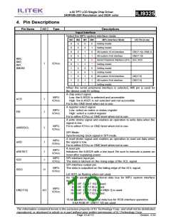
Pin Name
I/O
Type
Descriptions
Input Interface
Select the MPU system interface mode
IM3 IM2 IM1 IM0
MPU-Interface Mode
DB Pin in use
0
0
0
0
0
0
1
1
1
1
1
0
0
0
0
1
1
0
0
0
0
1
0
0
1
1
0
1
0
0
1
1
*
0
1
0
1
ID
*
Setting invalid
Setting invalid
i80-system 16-bit interface
i80-system 8-bit interface
DB[17:10], DB[8:1]
DB[17:10]
IM3,
IM2,
IM1,
IM0/ID
Serial Peripheral Interface (SPI) SDI, SDO
Setting invalid
I
IOVcc
0
1
0
1
*
Setting invalid
Setting invalid
i80-system 18-bit interface
i80-system 9-bit interface
Setting invalid
DB[17:0]
DB[17:9]
When the serial peripheral interface is selected, IM0 pin is used for
the device code ID setting.
A chip select signal.
MPU
IOVcc
Low: the ILI9325 is selected and accessible
High: the ILI9325 is not selected and not accessible
Fix to the GND level when not in use.
A register select signal.
Low: select an index or status register
High: select a control register
nCS
RS
I
I
MPU
IOVcc
Fix to either IOVcc or GND level when not in use.
A write strobe signal and enables an operation to write data when the
signal is low.
MPU
IOVcc
Fix to either IOVcc or GND level when not in use.
nWR/SCL
nRD
I
I
SPI Mode:
Synchronizing clock signal in SPI mode.
A read strobe signal and enables an operation to read out data when
the signal is low.
Fix to either IOVcc or GND level when not in use.
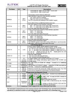
A reset pin.
Initializes the ILI9325 with a low input. Be sure to execute a power-on
reset after supplying power.
SPI interface input pin.
MPU
IOVcc
MPU
IOVcc
nRESET
SDI
I
I
MPU
IOVcc
The data is latched on the rising edge of the SCL signal.
SPI interface output pin.
MPU
IOVcc
The data is outputted on the falling edge of the SCL signal.
SDO
O
Let SDO as floating when not used.
An 18-bit parallel bi-directional data bus for MPU system interface
mode
8-bit I/F: DB[17:10] is used.
9-bit I/F: DB[17:9] is used.
16-bit I/F: DB[17:10] and DB[8:1] is used.
18-bit I/F: DB[17:0] is used.
MPU
IOVcc
DB[17:0]
I/O
18-bit parallel bi-directional data bus for RGB interface operation
6-bit RGB I/F: DB[17:12] are used.
The information contained herein is the exclusive property of ILI Technology Corp. and shall not be distributed,
reproduced, or disclosed in whole or in part without prior written permission of ILI Technology Corp.
Page 10 of 111
Version: 0.35

 ETC [ ETC ]