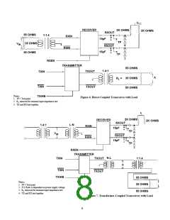
TXOUT
R
A
TERMINAL
L
TXOUT
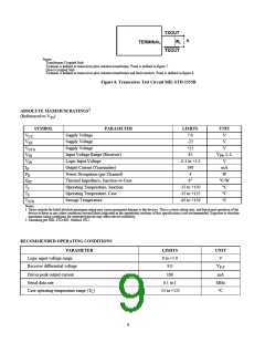
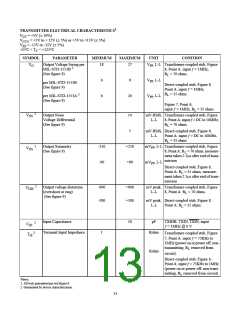
Notes:
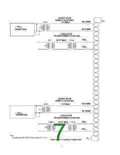
Transformer-Coupled Stub:
Terminal is defined as transceiver plus isolation transformer. Point A defined in figure 7.
Direct-Coupled Stub:
Terminal is defined as transceiver plus isolation transformer and fault resistors. Point A defined in figure 6.
Figure 8. Transceiver Test Circuit MIL-STD-1553B
1
ABSOLUTE MAXIMUM RATINGS
(Referenced to V
)
SS
SYMBOL
PARAMETER
LIMITS
UNIT
V
V
V
V
V
Supply Voltage
Supply Voltage
Supply Voltage
7.0
V
V
V
CC
EE
-22
+22
CCA
IN
Input Voltage Range (Receiver)
Logic Input Voltage
42
V , L-L
PP
-0.3 to +5.5
V
IN
I
Output Current (Transmitter)
Power Dissipation (per Channel)
Thermal Impedance, Junction-to-Case
Operating Temperature, Junction
Operating Temperature, Case
Storage Temperature
190
4
mA
W
O
P
D
2
Q
6
°C/W
°C
JC
T
T
T
-55 to +150
-55 to +125
-65 to +150
J
°C
C
°C
STG
Notes:
1. Stress outside the listed absolute maximum rating may cause permanent damage to the devices. This is a stress rating only, and functional operation of the
device at these or any other conditions beyond limits indicated in the operational sections of this specification is not recommended. Exposure to absolute
maximum rating conditions for extended periods may affect device reliability.
2. Mounting per MIL-STD-883, Method 1012.
RECOMMENDED OPERATING CONDITIONS
PARAMETER
Logic input voltage range
LIMITS
0 to +5.0
9.0
UNIT
V
Receiver differential voltage
V
P-P
Driver peak output current
Serial data rate
180
mA
MHz
°C
0.1 to 1
Case operating temperature range (T )
-55 to +125
C
9

 ETC [ ETC ]