CY545 Stepper System Controller
www.ControlChips.com
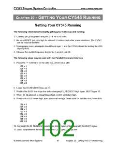
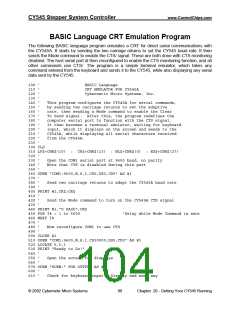
The following steps may be used with the Serial Command Interface.
12. Connect your serial port to the CY545 RxD and TxD signals, pins 10 and 11, with the proper
voltage translation buffers.
13. Send two carriage return codes to adapt the CY545 baud rate. The CRT emulation program
at the end of this section is useful for this purpose.
14. Send the command “+<cr>”.
15. The CCW signal (pin 2) will go from high to low.
16. Repeat the above command sequence with a “-<cr>” command. The ASCII code for “-” is
2Dh. The CCW signal will return high when this command is sent.
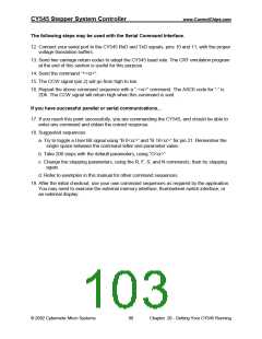
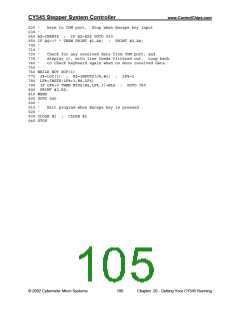
If you have successful parallel or serial communications...
17. If you reach this point successfully, you are commanding the CY545, and should be able to
enter any command and obtain the correct response.
18. Suggested sequences:
a. Try to toggle a User Bit signal using “B 0<cr>” and “B 16<cr>” for pin 21. Remember the
single space between the command letter and parameter value.
b. Take 200 steps with the default parameters, using “G<cr>”
c. Change the stepping parameters, using the R, F, S, and N commands, then try stepping
again.
d. Refer to examples in this manual for other command sequences.
19. After the initial checkout, use your own command sequences as required by the application.
You may need to exercise the external memory interface, thumbwheel switch interface, or
an external display.
© 2002 Cybernetic Micro Systems
98
Chapter 20 - Getting Your CY545 Running

 ETC [ ETC ]