CY545 Stepper System Controller
www.ControlChips.com
CHAPTER 20 - GETTING YOUR CY545 RUNNING
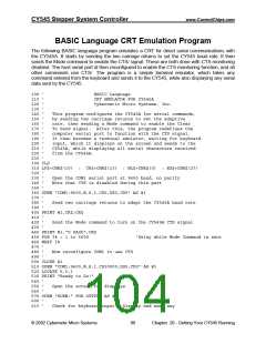
Getting Your CY545 Running
The following checklist will simplify getting your CY545 up and running.
1. Connect pin 20 to ground and pins 31 & 40 to +5 volts.
2. Be sure RESET (pin 9) is high for at least 10 milliseconds after power stabilizes. The CY545
can be reset at any time.
3. Upon proper reset, all outputs should be at logic 1, and the CY545 should be testing the JOG
signal (pin 6).
4. Observe the crystal frequency divided by 6 on ALE, pin 30.
The following steps may be used with the Parallel Command Interface.
5. Place the “+” command on the data bus, ASCII value 2Bh
D0 = 1
D1 = 1
D2 = 0
D3 = 1
D4 = 0
D5 = 1
D6 = 0
D7 = 0
6. Lower the IO_REQUEST line, pin 13.
7. Wait for the BUSY line to go low before bringing IO_REQUEST high again. BUSY is pin 15.
8. When IO_REQUEST is brought back high, BUSY will return high.
9. Wait for BUSY to return high, then place the carriage return code on the data bus, value 0Dh
D0 = 1
D1 = 0
D2 = 1
D3 = 1
D4 = 0
D5 = 0
D6 = 0
D7 = 0
10. Generate the IO_REQUEST handshake strobe again, interacting with the BUSY signal.
11. Upon completion of the above sequence, CCW (pin 2) will go low.
© 2002 Cybernetic Micro Systems
97
Chapter 20 - Getting Your CY545 Running

 ETC [ ETC ]