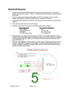
Wiring For RF Pickup Coil:
1. Connect a two conductor shielded cable from the pickup to Terminals 5 and 6. Connect the
shield to Terminal 4 (see Figure 1). NOTE: It is also preferable that the pickup coil be grounded
to the shield.
2. Connect a power source, which must be within 8-30 VDC, to Terminals 7 and 8. The Plus
voltage is connected to Terminal 8 and the Return to Terminal 7 (see Figure 1).
3. Connect the Pulse output wire to Terminal 3, and connect the Pulse common to Terminal 4 (see
Figure 1).
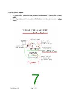
4. Set Jumper HD2 (see Figure 3) to the RF position.
5. Configure Jumper HD1 (see Figure 3) to the desired pulse output as follows:
Pulse Output Type
Open Collector
HD1 Jumper Configuration
JP2
Square Wave to Vin
TTL/CMOS
JP1 and JP2
JP1, JP2 and JP3
JP1, JP2 and JP4
0-10 VDC Square Wave
6. Install pickup (e.g. in meter) and provide power to PA1001A. Use a digital voltmeter set to DC
voltage and attach the positive lead to Terminal 6 and the common lead to Terminal 2. Adjust the
Carrier Adjustment (R2) (see Figure 3) to a reading of 3.00 VDC to fine-tune the pickup for air
gap, wall thickness, etc.
7. With power still supplied to PA1001A determine if pulse output is being generated in the absence
of motion. Adjust the RF Trigger (R24) (see Figure 3) clock wise until the false pulsation has
stopped. If pulsation continues when adjusted fully clock wise, check that all shields have been
properly terminated and grounded.
PA1001A – 7/02
Page 5 of 11

 ETC [ ETC ]