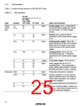
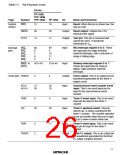
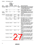
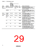
Table 1-2 Pin Functions (cont)
Pin No.
FP-100B
TFP-100B
Type
Symbol
TFP-100G
FP-100A
I/O
Name and Functions
Timer pins TMOFH
3
6
Output
Timer FH output: This is an output pin
for waveforms generated by the timer
FH output compare function.
TMIG
4
7
Input
Timer G capture input: This is an
input pin for timer G input capture.
14-bit
PWM pin
PWM
24
27
Output
14-bit PWM output: This is an output
pin for waveforms generated by the 14-
bit PWM
I/O ports PB7 to PB0 95 to 88
PC3 to PC0 99 to 96
98 to 91
Input
Input
Port B: This is an 8-bit input port.
Port C: This is a 4-bit input port.
2, 1,
100, 99
P43
86
89
Input
I/O
Port 4 (bit 3): This is a 1-bit input port.
P42 to P40 85 to 83
PA3 to PA0 39 to 42
P17 to P10 8 to 1
88 to 86
Port 4 (bits 2 to 0): This is a 3-bit I/O
port. Input or output can be
designated for each bit by means of
port control register 4 (PCR4).
42 to 45
11 to 4
I/O
I/O
I/O
I/O
I/O
Port A: This is a 4-bit I/O port. Input or
output can be designated for each bit
by means of port control register A
(PCRA).
Port 1: This is an 8-bit I/O port. Input
or output can be designated for each
bit by means of port control register 1
(PCR1).
P27 to P20 23 to 16
P37 to P30 31 to 24
P57 to P50 50 to 43
26 to 19
34 to 27
53 to 46
Port 2: This is an 8-bit I/O port. Input
or output can be designated for each
bit by means of port control register 2
(PCR2).
Port 3: This is an 8-bit I/O port. Input
or output can be designated for each
bit by means of port control register 3
(PCR3).
Port 5: This is an 8-bit I/O port. Input
or output can be designated for each
bit by means of port control register 5
(PCR5).
12

 ETC [ ETC ]