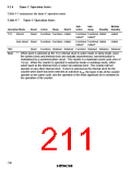
3. Pin configuration
Table 9-8 shows the timer F pin configuration.
Table 9-8 Pin Configuration
Name
Abbrev.
TMIF
I/O
Function
Timer F event input
Timer FH output
Timer FL output
Input
Output
Output
Event input pin for input to TCFL
Timer FH toggle output pin
Timer FL toggle output pin
TMOFH
TMOFL
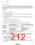
4. Register configuration
Table 9-9 shows the register configuration of timer F.
Table 9-9 Timer F Registers
Name
Abbrev.
TCRF
R/W
W
Initial Value
H'00
Address
H'FFB6
H'FFB7
H'FFB8
H'FFB9
H'FFBA
H'FFBB
H'FFFA
Timer control register F
Timer control/status register F
8-bit timer counter FH
8-bit timer counter FL
Output compare register FH
Output compare register FL
Clock stop register 1
TCSRF
TCFH
R/W
R/W
R/W
R/W
R/W
R/W
H'00
H'00
TCFL
H'00
OCRFH
OCRFL
CKSTPR1
H'FF
H'FF
H'FF
199

 ETC [ ETC ]