SERIES
12 PIN, 10 AMP, TIME DELAY RELAY
236/237/238
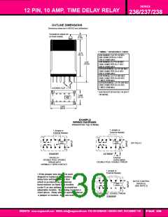
OUTLINE DIMENSIONS
Dimensions shown are in INCHES and (millimeters)
Screwdriver adjust not
on fixed models.
.313
(7.95)
✝ TIMING * RESISTANCE CHART
3.75
(95.2)
236 RANGE: O.2 TO 12 SEC
20K OHMS PER EA.3 SEC
100 K OHMS MAX.
236 RANGE: 0.2 TO 20 SEC
100K OHMS PER EA.7 SEC
500 K OHMS MAX
4.56
(115.8)
237/238 RANGE: 0.2 TO 20 SEC.
100K OHMS PER EA.6 SEC
500 K OHMS MAX.
236 RANGE: 2.0 TO 200 SEC
200K OHMS PER EA.60 SEC
1 MEG OHM MAX.
237/238 RANGE: 2.0 TO 200 SEC
200K OHMS PER EA.55 SEC.
1 MEG OHM MAX.
LOCKING CLIP
* USE RESISTOR RATED 1/4 WATT
OR MORE.
1.468
(37.2)
1
6
7
12
2.625
(66.6)
EXAMPLE
WIRING DIAGRAMS
Viewed from Top of Relay
✝ Jumper or
External Resistor
✝ Jumper or
External Resistor
12
1
12
7
-
7 -
TIMING
TIMING
MODULE
MODULE
OFF DELAY
+
6
+
6
1
236ABXP
237XBXP
ON DELAY
DOUBLE POLE DOUBLE
THROW WITH
External
control switch
DOUBLE POLE DOUBLE THROW
NORMALLY OPEN CONTACT
✝ Jumper or
External Resistor
✝ If the jumper wire shown in each
diagram is replaced by a resistor,
delay time will be added to that
-
12
1
7
BATCH CONTROL
INTERVAL
(SEE NOTE 3)
which is produced by an internal
TIMING
MODULE
fixed resistor on fixed time models
(code F) or any setting on screwdriver
adjustable models. See timing resistance
chart above. Relay will not operate without
a jumper or resistor. Also see note 1.
+
6
DOUBLE POLE DOUBLE THROW
238XBXP
WEBSITE: www.magnecraft.com EMAIL:info@magnecraft.com FAX ON DEMAND 1-800/891-2957, DOCUMENT 100
PAGE 130

 ETC [ ETC ]