Si3210/Si3211/Si3212
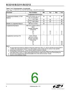
Table 3. AC Characteristics (Continued)
(V
, V
= 3.13 to 5.25 V, T = 0 to 70°C for K-Grade, –40 to 85°C for B-Grade)
DDA
DDD A
Parameter
Test Condition
Min
Typ
Max
Unit
Longitudinal Performance
Longitudinal to Metallic or PCM
Balance
200 Hz to 3.4 kHz, β
≥
56
60
—
dB
Q1,Q2
150, 1% mismatch
5
β
= 60 to 240
43
53
40
60
60
—
—
—
—
dB
dB
dB
Q1,Q2
5
β
= 300 to 800
Q1,Q2
Metallic to Longitudinal Balance
Longitudinal Impedance
200 Hz to 3.4 kHz
200 Hz to 3.4 kHz at TIP or
RING
Register selectable
ETBO/ETBA
00
01
10
—
—
—
33
17
17
—
—
—
Ω
Ω
Ω
Longitudinal Current per Pin
Active off-hook
200 Hz to 3.4 kHz
Register selectable
ETBO/ETBA
—
—
—
4
8
8
—
—
—
mA
mA
mA
00
01
10
Notes:
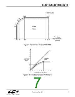
1. The input signal level should be 0 dBm0 for frequencies greater than 100 Hz. For 100 Hz and below, the level should be
–10 dBm0. The output signal magnitude at any other frequency will be smaller than the maximum value specified.
2. Analog signal measured as V
– V
. Assumes ideal line impedance matching.
TIP
RING
3. The quantization errors inherent in the µ/A-law companding process can generate slightly worse gain tracking performance
in the signal range of 3 dB to –37 dB for signal frequencies that are integer divisors of the 8 kHz PCM sampling rate.
4. The level of any unwanted tones within the bandwidth of 0 to 4 kHz does not exceed –55 dBm.
5. Assumes normal distribution of betas.
6
Preliminary Rev. 1.11

 ETC [ ETC ]