PRELIMINARY
PCT1789W DATA SHEET
PCT303DW FUNCTIONAL DESCRIPTION
!!
Table 8 Line Interface Configurations (Register 16)
AC
Mode 2
12
11
Termina-
tion
DC Termination
Country
Bit 5
Bit 4
Bit 3
10
9
1. FCC
0
1
0
1
0
1
1
1
0
0
1
0
1
1
0
1
1
0
1
0
1
2. Australia
3. Japan
8
4. New Zealand
5. Singapore a
6. South Africa
7. CTR21 b,c
7
6
.01 .02 .03 .04 .05 .06 .07 .08 .09 .1 .11
Loop Current (A)
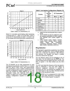
Figure 8 Mode 2 I/V Characteristics (1,0)
a. Support for loop currents greater than or equal to
20 mA.
b. The PCT303DW can also be configured to meet
the individual specifications for these countries.
(See “Appendix: NET4 Country Support” on
page 65.)
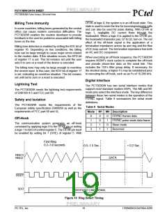
Mode 3 (1,1) provides current limiting, while maintaining
a transmit level of –1 dBm at Tip and Ring. Figure 9
shows the I/V characteristics of mode 3. In mode 3, the
DC termination will current limit before reaching 60 mA.
c. CTR21 includes Austria, Belgium, Denmark,
Finland, France, Germany, Greece, Hungary,
Mode 3
45
Iceland,
Ireland,
Italy,
Liechtenstein,
40
Luxembourg, Netherlands, Norway, Portugal,
Spain, Sweden, Switzerland, and the UK.
35
30
25
Ring Detection
The ring signal is capacitively coupled from Tip and Ring
to the RNG1 and RNG2 pins. The PCT303DW supports
either full- or half-wave ring detection. With full-wave
ring detection, the designer can detect a polarity
reversal as well as the ring signal.
20
15
10
5
.015
.055 .06
The ring detector output can be monitored in one of
three ways. The first method uses the RGDT pin. The
second method uses the register bits RDTP, RDTN, and
RDT of register 5. The final method uses the SDO
output.
.02 .025 .03 .035 .04 .045 .05
Loop Current (A)
Figure 9 Mode 3 I/V Characteristics (1,1)
The PCT303DW can be fully programmed to meet
international requirements, and the device is compliant
with FCC, NET4, CTR21, JATE, and country-specific
PTT specifications. Figure 2 outlines a limited set of line
interface configurations required to support CTR21 and
other key countries by setting different AC and DC
termination modes. See “Appendix: NET4 Country
Support” on page 65 for a more complete set of the line
interface configurations required to support NET4
countries.
The DSP must detect the frequency of the ring signal in
order to distinguish a ring from pulse dialing by
telephone equipment connected in parallel. If
necessary, the DSP can estimate the amplitude of the
ring signal based on the ring detect threshold and the
duty cycle of the ring detector output.
The PCT303DW can be programmed for both ringer
impedance and ringer threshold as described in the
“Appendix: NET4 Country Support” on page 65.
PRELIMINARY
PC-TEL, Inc.
18
1789W0DOCDAT06A-0299

 ETC [ ETC ]