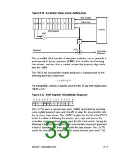
Figure 2.11 Scrambler Basic Serial Architecture
Shift_Enable
Initial Load
15 14 13 12 11 10 9
8
7
6
5 4 3 2 1
Control
Shift Register
XOR
&
XOR
Bitstream
Scrambled
Bitstream
The scrambler block consists of two major modules: one to generate a
pseudo-random binary sequence (PRBS) that modifies the incoming
data stream, and the other a control module that properly aligns data
with the PRBS.
The PRBS the descrambler module produces is characterized by the
following generator polynomial:
14
15
1 + x + x
For initialization, choose a specific value for the 15-tap shift register (see
Figure 2.12).
Figure 2.12 Shift Register Initialization Sequence
0
0
0
0
0
0
0
1
8
0
7
1
6
0
5
1 0
0
2
1
1
15 14 13 12 11 10 9
4 3
The L64777 uses a special sync word (0xB8), generated by inverting
every eighth transport sync word (0x47), to align the descrambler with
the incoming data stream. The L64777 applies the first bit of the PRBS
to the first data bit following the inverted sync byte and freezes the
scrambler register contents during gaps for RS check words. During the
following noninverted sync words, the descrambler sequence generator
is kept in operation but does not modify the data stream. The L64777
resets the descrambler sequence after every inverted sync word. The
Sync/EF Reinsertion Unit
2-19

 ETC [ ETC ]