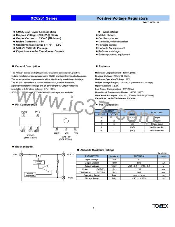
XC6201 Series
Positive Voltage Regulators
Electrical Characteristics
XC6201P272
VOUT(T) = 2.7V
PARAMETER
SYMBOL
CONDITIONS
MIN
TYP
MAX
UNITS CIRCUIT
2.646
2.700
2.754
Output Voltage
VOUT(E)
(Note2)
IOUT=40mA
VIN=3.7V
V
2
Maximum Output Current
Load Regulation
IOUT max
VIN=4.0V, VOUT(E) ≥ 2.43V
100
mA
mV
2
2
∆VOUT
VIN=4.0V
1mA ≤ IOUT≤ 80mA
15
40
Vdif1
Vdif2
ISS
IOUT=80mA
IOUT=160mA
VIN=4.0V
IOUT=40mA
4.0V ≤ VIN ≤ 10.0V
200
450
2.0
370
710
5.0
mV
2
2
1
Dropout Voltage (Note 3)
mV
µA
Supply Current
Line Regulation
∆VOUT
∆VIN · VOUT
VIN
0.2
0.3
%/V
2
Input Voltage
Output Voltage
Temperature Characteristics
10
V
-
IOUT=40mA
-40OC ≤ Topr ≤ 85OC
±100
ppm/OC
∆VOUT
∆Topr · VOUT
2
XC6201P332
VOUT(T) = 3.3V
PARAMETER
SYMBOL
CONDITIONS
MIN
TYP
MAX
UNITS CIRCUIT
3.234
3.300
3.366
Output Voltage
VOUT(E)
(Note2)
IOUT=40mA
VIN=4.3V
V
2
Maximum Output Current
Load Regulation
IOUT max
VIN=4.3V, VOUT(E) ≥ 2.97V
150
mA
mV
2
2
∆VOUT
VIN=4.3V
1mA ≤ IOUT≤ 80mA
20
50
Vdif1
Vdif2
ISS
IOUT=80mA
IOUT=160mA
VIN=4.3V
IOUT=40mA
4.3V ≤ VIN ≤ 10.0V
200
450
2.0
360
700
5.0
mV
2
2
1
Dropout Voltage (Note 3)
mV
µA
Supply Current
Line Regulation
∆VOUT
∆VIN · VOUT
VIN
0.2
0.3
%/V
2
Input Voltage
Output Voltage
Temperature Characteristics
10
V
-
IOUT=40mA
-40OC ≤ Topr ≤ 85OC
±100
ppm/OC
∆VOUT
∆Topr · VOUT
2
XC6201P502
VOUT(T) = 5.0V
PARAMETER
SYMBOL
CONDITIONS
MIN
TYP
MAX
UNITS CIRCUIT
4.900
5.000
5.100
Output Voltage
VOUT(E)
(Note2)
IOUT=40mA
VIN=6.0V
V
2
Maximum Output Current
Load Regulation
IOUT max
VIN=6.0V, VOUT(E) ≥ 4.5V
200
mA
mV
2
2
∆VOUT
VIN=6.0V
1mA ≤ IOUT≤ 100mA
30
70
Vdif1
Vdif2
ISS
IOUT=100mA
IOUT=200mA
VIN=6.0V
IOUT=40mA
6.0V ≤ VIN ≤ 10.0V
160
400
2.0
340
600
6.0
mV
2
2
1
Dropout Voltage (Note 3)
mV
µA
Supply Current
Line Regulation
∆VOUT
∆VIN · VOUT
VIN
0.2
0.3
%/V
2
Input Voltage
Output Voltage
Temperature Characteristics
10
V
-
IOUT=40mA
-40OC ≤ Topr ≤ 85OC
±100
ppm/OC
∆VOUT
∆Topr · VOUT
2
Note : 1. VOUT(T) = Specified Output Voltage.
2. VOUT(E) = Effective Output Voltage (i.e. the output voltage when "VOUT(T)+1.0V" is provided while maintaining a certain IOUT value).
3. Vdif = { VIN1 (Note5) - VOUT1 (Note4) }
4. VOUT1 = A voltage equal to 98% of the output voltage when a stabilised ( VOUT (T) + 1.0V ) is input.
5. VIN1 = The input voltage at the time VOUT1 is output (input voltage has been gradually reduced).
2

 ETC [ ETC ]