Global Mixed-mode Technology Inc.
G781
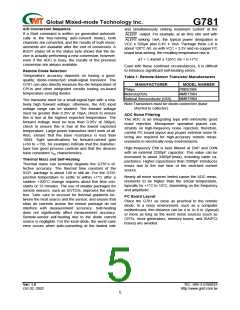
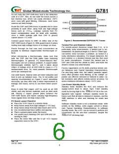
Do not route the DXP-DXN lines next to the deflection
coils of a CRT. Also, do not route the traces across a
fast memory bus, which can easily introduce +30°C
error, even with good filtering, Otherwise, most noise
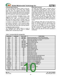
GND
DXP
DXN
GND
10 MILS
MINIMUM
10 MILS
10 MILS
sources are fairly benign.
Route the DXP and DXN traces in parallel and in close
proximity to each other, away from any high-voltage
10 MILS
traces such as +12VDC. Leakage currents from PC
board contamination must be dealt with carefully,
since a 10MΩ leakage path from DXP to ground
causes about +1°C error.
Figure 2. Recommended DXP/DXN PC Traces
Connect guard traces to GND on either side of the
DXP-DXN traces (Figure 2). With guard traces in place,
routing near high-voltage traces is no longer an issue.
Twisted Pair and Shielded Cables
For remote-sensor distances longer than 8 in., or in
particularly noisy environments, a twisted pair is rec-
ommended. Its practical length is 6 feet to 12feet (typi
cal) before noise becomes a problem, as tested in a
noisy electronics laboratory. For longer distances, the
best solution is a shielded twisted pair like that used
for audio microphones. Connect the twisted pair to
DXP and DXN and the shield to GND, and leave the
shield’s remote end unterminated.
Route through as few vias and crossunders as
possible to minimize copper/solder thermocouple ef-
fects.
When introducing a thermocouple, make sure that
both the DXP and the DXN paths have matching
thermocouples. In general, PC board-induced ther-
mocouples are not a serious problem, A copper-solder
thermocouple exhibits 3µV/°C, and it takes about
240µV of voltage error at DXP-DXN to cause a +1°C
measurement error. So, most parasitic thermocouple
errors are swamped out.
Excess capacitance at DX_limits practical remote sen-
sor distances (see Typical Operating Characteristics),
For very long cable runs, the cable’s parasitic capaci-
tance often provides noise filtering, so the 2200pF ca-
pacitor can often be removed or reduced in value. Ca-
ble resistance also affects remote-sensor accuracy; 1Ω
series resistance introduces about + 0.6°C error.
Use wide traces. Narrow ones are more inductive and
tend to pick up radiated noise. The 10 mil widths and
spacing recommended on Figure 2 aren’t absolutely
necessary (as they offer only a minor improvement in
leakage and noise), but try to use them where practi-
cal.
Low-Power Standby Mode
Standby mode disables the ADC and reduces the
supply-current drain to about 10µA. Enter standby
Keep in mind that copper can’t be used as an EMI
shield, and only ferrous materials such as steel work
will. Placing a copper ground plane between the
DXP-DXN traces and traces carrying high-frequency
noise signals does not help reduce EMI.
mode by forcing high to the RUN/STOP bit in the con-
figuration byte register. Software standby mode be-
haves such that all data is retained in memory, and the
SMB interface is alive and listening for reads and
writes.
PC Board Layout Checklist
ꢀPlace the G781 close to a remote diode.
ꢀKeep traces away from high voltages (+12V bus).
ꢀKeep traces away from fast data buses and CRTs.
ꢀUse recommended trace widths and spacing.
ꢀPlace a ground plane under the traces
ꢀUse guard traces flanking DXP and DXN and con
necting to GND.
Software standby mode is not a shutdown mode. With
activity on the SMBus, extra supply current is drawn
(see Typical Operating Characteristics). In software
standby mode, the G781 can be forced to perform A/D
conversions via the one-shot command, despite the
RUN/STOP bit being high.
ꢀPlace the noise filter and the 0.1µF VCC bypass
capacitors close to the G781.
Ver: 1.0
TEL: 886-3-5788833
http://www.gmt.com.tw
Oct 02, 2002
6

 ETC [ ETC ]