Global Mixed-mode Technology Inc.
G781
A/D Conversion Sequence
and simultaneously sinking maximum current at the
ALERT output. For example, at an 8Hz rate and with
If a Start command is written (or generated automati-
cally in the free-running auto-convert mode), both
channels are converted, and the results of both meas-
urements are available after the end of conversion. A
BUSY status bit in the status byte shows that the de-
vice is actually performing a new conversion; however,
even if the ADC is busy, the results of the previous
conversion are always available.
ALERT sinking 1mA, the typical power dissipation is
VCC x 320µA plus 0.4V x 1mA. Package theta J-A is
about 120°C /W, so with VCC = 3.3V and no copper PC
board heat-sinking, the resulting temperature rise is:
dT = 1.45mW x 120°C /W = 0.17°C
Even with these contrived circumstances, it is difficult
to introduce significant self-heating errors.
Remote Diode Selection
Temperature accuracy depends on having a good-
quality, diode-connected small-signal transistor. The
G781 can also directly measure the die temperature of
CPUs and other integrated circuits having on-board
temperature-sensing diodes.
Table 1. Remote-Sensor Transistor Manufacturers
MANUFACTURER
MODEL NUMBER
PMBS3904
Philips
Motorola(USA)
MMBT3904
National Semiconductor (USA)
MMBT3904
The transistor must be a small-signal type with a rela-
tively high forward voltage; otherwise, the A/D input
voltage range can be violated. The forward voltage
must be greater than 0.25V at 10µA; check to ensure
this is true at the highest expected temperature. The
forward voltage must be less than 0.95V at 300µA;
check to ensure this is true at the lowest expected
temperature. Large power transistors don’t work at all.
Also, ensure that the base resistance is less than
100Ω. Tight specifications for forward-current gain
(+50 to +150, for example) indicate that the manufac-
turer has good process controls and that the devices
have consistent Vbe characteristics.
Note:Transistors must be diode-connected (base
shorted to collector).
ADC Noise Filtering
The ADC is an integrating type with inherently good
noise rejection. Micropower operation places con-
straints on high-frequency noise rejection; therefore,
careful PC board layout and proper external noise fil-
tering are required for high-accuracy remote meas-
urements in electrically noisy environments.
High-frequency EMI is best filtered at DXP and DXN
with an external 2200pF capacitor. This value can be
increased to about 3300pF(max), including cable ca-
pacitance. Higher capacitance than 3300pF introduces
errors due to the rise time of the switched current
source.
Thermal Mass and Self-Heating
Thermal mass can seriously degrade the G781’s ef-
fective accuracy. The thermal time constant of the
SOP- package is about 140 in still air. For the G781
junction temperature to settle to within +1°C after a
sudden +100°C change requires about five time con-
stants or 12 minutes. The use of smaller packages for
remote sensors, such as SOT23s, improves the situa-
tion. Take care to account for thermal gradients be-
tween the heat source and the sensor, and ensure that
stray air currents across the sensor package do not
interfere with measurement accuracy. Self-heating
does not significantly affect measurement accuracy.
Remote-sensor self-heating due to the diode current
source is negligible. For the local diode, the worst-case
error occurs when auto-converting at the fastest rate
Nearly all noise sources tested cause the ADC meas-
urements to be higher than the actual temperature,
typically by +1°C to 10°C, depending on the frequency
and amplitude.
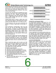
PC Board Layout
Place the G781 as close as practical to the remote
diode. In a noisy environment, such as a computer
motherboard, this distance can be 4 in. to 8 in. (typical)
or more as long as the worst noise sources (such as
CRTs, clock generators, memory buses, and ISA/PCI
buses) are avoided.
Ver: 1.0
TEL: 886-3-5788833
http://www.gmt.com.tw
Oct 02, 2002
5

 ETC [ ETC ]