Global Mixed-mode Technology Inc.
G781
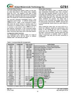
Table 6. Configuration-Byte Bit Assignments
BIT
7 (MSB)
NAME
MASK
RUN /
STOP
RFU
POR STATE
FUNCTION
0
Masks all ALERT interrupts when high.
Standby mode control bit. If high, the device immediately stops converting and en-
ters standby mode. If low, the device converts in either one-shot or timer mode.
6
0
0
5-0
Reserved for future use
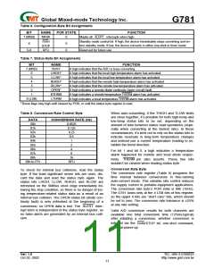
Table 7. Status-Byte Bit Assignments
BIT
7 (MSB)
NAME
BUSY
FUNCTION
A high indicates that the ADC is busy converting.
6
5
4
3
2
1
LHIGH*
LLOW*
RHIGH*
RLOW*
OPEN*
RTHRM
LTHRM
A high indicates that the local high-temperature alarm has activated.
A high indicates that the local low-temperature alarm has activated.
A high indicates that the remote high-temperature alarm has activated.
A high indicates that the remote low-temperature alarm has activated.
A high indicates a remote-diode continuity (open-circuit) fault.
A high indicates a remote temperature THERM alarm has activated.
A high indicates a local temperature THERM alarm has activated.
0 (LSB)
*These flags stay high until cleared by POR, or until the status byte register is read.
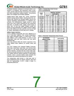
Table 8. Conversion-Rate Control Byte
When auto-converting, if the THIGH and TLOW limits
are close together, it’s possible for both high-temp and
low-temp status bits to be set, depending on the
amount of time between status read operations (espe-
cially when converting at the fastest rate). In these
circumstances, it’s best not to rely on the status bits to
indicate reversals in long-term temperature changes
and instead use a current temperature reading to es-
tablish the trend direction.
DATA
00h
01h
02h
03h
CONVERSION RATE (Hz)
0.0625
0.125
0.25
0.5
1
04h
05h
2
06h
4
For bit 1 and bit 0, a high indicates a temperature
alarm happened for remote and local diode respec-
tively. THERM pin also asserts. These two bits
wouldn’t be cleared when reading status byte.
07h
8
08h
16
09h to FFh
RFU
Conversion Rate Byte
To check for internal bus collisions, read the status
byte. If the least significant seven bits are ones, dis-
card the data and read the status byte again. The
status bits LHIGH, LLOW, RHIGH, and RLOW are
refreshed on the SMBus clock edge immediately fol-
lowing the stop condition, so there is no danger of los-
ing temperature-related status data as a result of an
internal bus collision. The OPEN status bit (diode con-
tinuity fault) is only refreshed at the beginning of a
The conversion rate register (Table 8) programs the
time interval between conversions in free-running
auto-convert mode. This variable rate control reduces
the supply current in portable-equipment applications.
The conversion rate byte’s POR state is 08h (16Hz).
The G781 looks only at the 4 LSB bits of this register,
so the upper 4 bits are “don’t care” bits, which should
be set to zero. The conversion rate tolerance is 25%
at any rate setting.
conversion, so OPEN data is lost. The
inter-
ALERT
rupt latch is independent of the status byte register, so
no false alerts are generated by an internal bus colli-
sion.
Valid A/D conversion results for both channels are
available one total conversion time (125ms,typical)
after initiating a conversion, whether conversion is
initiated via the RUN/STOP bit, one-shot command,
or initial power-up.
Ver: 1.0
TEL: 886-3-5788833
http://www.gmt.com.tw
Oct 02, 2002
11

 ETC [ ETC ]