U62H64
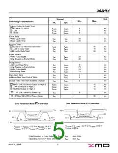
Test Configuration for Functional Check
5 V
VCC
A0
A1
A2
A3
DQ0
DQ1
DQ2
DQ3
DQ4
DQ5
DQ6
DQ7
A4
481
A5
VIH
VIL
A6
A7
A8
A9
A10
A11
A12
VO
30 pF e
E1
E2
W
255
VSS
G
e In measurement of tdis(E), tdis(W), tdis(G), ten(E), ten(W), ten(G) the capacitance is 5 pF.
Capacitance
Conditions
VCC = 5.0 V
Symbol
Min.
Max.
Unit
Input Capacitance
CI
8
pF
VI = VSS
f
= 1 MHz
Output Capacitance
CO
10
pF
Ta = 25 °C
All pins not under test must be connected with ground by capacitors.
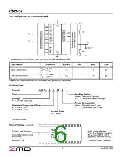
Ordering Code
Example
U62H64
S
K
35
L
Type
Leadfree Option
blank= Standard Package
Package
G1 = Leadfree Green Package f
S = SOP28 (300 mil)
Power Consumption
Operating Temperature Range
K = -40 to 85 °C
blank= Standard (only A-Type)
L
= Low Power (only K-Type)
A = -40 to 125 °C
Access Time
35 = 35 ns
f on special request
Device Marking (example)
ZMD
Product specification
Date of manufacture
U62H64SK
35L C 0425
(The first 2 digits indicating
the year, and the last 2
digits the calendar week.)
Assembly location and
trace code
1 ZZ
G1
Internal Code
Leadfree Green Package
6
April 20, 2004

 ZMD [ Zentrum Mikroelektronik Dresden AG ]