YB1517
Step-up DC-DC Converter & White LED Driver
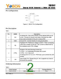
Pin Configuration
Figure 3 : YB1517 Pin Configuration
Pin Description
Table 1
Pin
NAME
Description
Switching Pin. This is the collector of the internal NPN power
SW
switch. Connect to inductor and diode. Minimize the metal
trace area connected to this pin to reduce EMI.
1
GND
FB
Ground Pin. Connect directly to local ground plane.
2
3
Feedback Pin. Reference voltage is 220mV. When connecting
LEDs and a resistor at this pin, LED current is determined by
the resistance and CTRL voltage.
Shutdown Pin and Dimming Control pin.
VCTRL > 1.8V generates full-scale LED current
VCTRL < 0.4V chip is off
CTRL
VIN
4
5
Switching from 0.4V to 2.0V, PWM duty cycle controls the LED
current
Input Supply Pin. Bypass this pin with a capacitor as close to
the device as possible
Ordering Information
Table 2
Order Number
Supplied as
Package Marking
YB1517ST25
3000 units Tape & Reel
Y58 F
YB1517 MRev.1.0
www.yobon.com.tw
2

 YOBON [ YOBON TECHNOLOGIES,INC. ]