4
0
R
Virtex-II Platform FPGAs:
Functional Description
DS031-2 (v3.5) November 5, 2007
Product Specification
Detailed Description
Input/Output Blocks (IOBs)
Table 1: Supported Single-Ended I/O Standards
Board
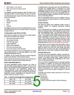
Virtex-II™ I/O blocks (IOBs) are provided in groups of two or
four on the perimeter of each device. Each IOB can be used
as input and/or output for single-ended I/Os. Two IOBs can
be used as a differential pair. A differential pair is always
connected to the same switch matrix, as shown in Figure 1.
IOSTANDARD Output
Input
VCCO
Input
VREF
Termination
Attribute
VCCO
3.3
3.3
2.5
1.8
1.5
3.3
3.3
3.3
Voltage (VTT
N/R
N/R
N/R
N/R
N/R
N/R
N/R
N/R
1.2
)
LVTTL
3.3
3.3
2.5
1.8
1.5
3.3
3.3
3.3
N/R (3)
N/R
N/R
N/R
N/R
N/R
N/R
N/R
0.8
LVCMOS33
LVCMOS25
LVCMOS18
LVCMOS15
PCI33_3
IOB blocks are designed for high performances I/Os, sup-
porting 19 single-ended standards, as well as differential
signaling with LVDS, LDT, Bus LVDS, and LVPECL.
IOB
PCI66_3
PAD4
Differential Pair
PCI-X
IOB
GTL
Note (1) Note (1)
Note (1) Note (1)
PAD3
Switch
GTLP
1.0
1.5
Matrix
IOB
PAD2
HSTL_I
1.5
1.5
1.5
1.5
1.8
1.8
1.8
1.8
1.8
1.8
2.5
2.5
3.3
3.3
3.3
N/R
N/R
N/R
N/R
N/R
N/R
N/R
N/R
N/R
N/R
N/R
N/R
N/R
N/R
N/R
0.75
0.75
0.9
0.75
0.75
1.5
HSTL_II
Differential Pair
IOB
PAD1
HSTL_III
HSTL_IV
HSTL_I_18
HSTL_II_18
HSTL_III _18
HSTL_IV_18
SSTL18_I(2)
SSTL18_II
SSTL2_I
0.9
1.5
DS031_30_101600
0.9
0.9
Figure 1: Virtex-II Input/Output Tile
Note: Differential I/Os must use the same clock.
0.9
0.9
1.1
1.8
Supported I/O Standards
1.1
1.8
Virtex-II IOB blocks feature SelectI/O-Ultra inputs and out-
puts that support a wide variety of I/O signaling standards.
In addition to the internal supply voltage (V
0.9
0.9
= 1.5V),
0.9
0.9
CCINT
output driver supply voltage (V
) is dependent on the I/O
CCO
1.25
1.25
1.5
1.25
1.25
1.5
standard (see Table 1 and Table 2). An auxiliary supply volt-
age (V = 3.3 V) is required, regardless of the I/O
standard used. For exact supply voltage absolute maximum
ratings, see DC Input and Output Levels in Module 3.
SSTL2_II
SSTL3_I
CCAUX
SSTL3_II
AGP-2X/AGP
Notes:
1.5
1.5
All of the user IOBs have fixed-clamp diodes to V
and to
CCO
1.32
N/R
ground. As outputs, these IOBs are not compatible or com-
pliant with 5V I/O standards. As inputs, these IOBs are not
normally 5V tolerant, but can be used with 5V I/O standards
when external current-limiting resistors are used. For more
details, see the “5V Tolerant I/Os“ Tech Topic at www.xil-
inx.com.
1. VCCO of GTL or GTLP should not be lower than the termination
voltage or the voltage seen at the I/O pad. Example: If the pin High
level is 1.5V, connect VCCO to 1.5V.
2. SSTL18_I is not a JEDEC-supported standard.
3. N/R = no requirement.
Table 3 lists supported I/O standards with Digitally Con-
trolled Impedance. See Digitally Controlled Impedance
(DCI), page 8.
© 2000–2007 Xilinx, Inc. All rights reserved. XILINX, the Xilinx logo, the Brand Window, and other designated brands included herein are trademarks of Xilinx, Inc. All other
trademarks are the property of their respective owners.
DS031-2 (v3.5) November 5, 2007
Product Specification
www.xilinx.com
Module 2 of 4
1

 XILINX [ XILINX, INC ]