WM8904
Pre-Production
DESCRIPTION
REGISTER
ADDRESS
BIT
LABEL
DEFAULT
R69 (45h)
Time between periodic updates for
LINEOUTL/LINEOUTR. Time is
calculated as 0.256s x (2^PERIOD)
11:8
DCS_TIMER_PE
RIOD_23 [3:0]
1010
DC Servo 2
0000 = Off
0001 = 0.52s
1010 = 266s (4min 26s)
1111 = 8519s (2hr 22s)
Time between periodic updates for
HPOUTL/HPOUTR. Time is calculated
as 0.256s x (2^PERIOD)
3:0
DCS_TIMER_PE
RIOD_01 [3:0]
1010
0000 = Off
0001 = 0.52s
1010 = 266s (4min 26s)
1111 = 8519s (2hr 22s)
Table 53 DC Servo Active Modes
DC SERVO READBACK
The current DC offset value for each Line and Headphone output channel can be read in two’s
complement format from the DCS_DAC_WR_VAL_n [7:0] bit fields in Registers R73, R74, R75 and
R76. Note that these values may form the basis of settings that are subsequently used by the DC
Servo in DAC Write mode.
DIGITAL AUDIO INTERFACE
The digital audio interface is used for inputting DAC data to the WM8904 and outputting ADC data
from it. The digital audio interface uses four pins:
ADCDAT: ADC data output
DACDAT: DAC data input
LRCLK: Left/Right data alignment clock
BCLK: Bit clock, for synchronisation
The clock signals BCLK and LRCLK can be outputs when the WM8904 operates as a master, or
inputs when it is a slave (see “Master and Slave Mode Operation”, below).
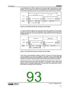
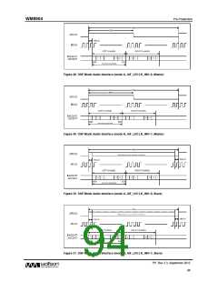
Four different audio data formats are supported:
Left justified
Right justified
I2S
DSP mode
All four of these modes are MSB first. They are described in “Audio Data Formats (Normal Mode)”,
below. Refer to the “Signal Timing Requirements” section for timing information.
Time Division Multiplexing (TDM) is available in all four data format modes. The WM8904 can be
programmed to send and receive data in one of two time slots.
PCM operation is supported using the DSP mode.
PP, Rev 3.3, September 2012
90
w

 WOLFSON [ WOLFSON MICROELECTRONICS PLC ]