WM8805
Production Data
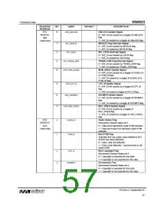
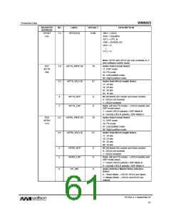
REGISTER
ADDRESS
BIT
LABEL
DEFAULT
DESCRIPTION
R29
SPDRX1
1Dh
2:0
READMUX
[2:0]
000
Interrupt Status Register Select
Determines which status register is to be read
back:
000 = Interrupt Status Register
001 = Channel Status Register 1
010 = Channel Status Register 2
011 = Channel Status Register 3
100 = Channel Status Register 4
101 = Channel Status Register 5
110 = S/PDIF Status Register
Continuous Read Enable
3
4
5
CONT
0
0
0
0 = Continuous read-back mode disabled
1 = Continuous read-back mode enabled
‘With Flags’ Mode Select
WITHFLAG
SPDGPO
0: ‘With Flags’ Mode disabled
1: ‘With Flags’ Mode enabled
RX4-7 Configuration Select
When set high the pin is a GPO pin.
0 – S/PDIF inputs
1 – GPO outputs
6
7
WL_MASK
0
1
S/PDIF Receiver Word Length Truncation
Mask
0 = disabled, data word is truncated as
described in Table 44.
1 = enabled, data word is not truncated.
SPD_192K_EN
S/PDIF Receiver 192kHz Support Enable
0 = disabled, S/PDIF receiver maximum
supported sampling frequency is 96kHz
1 = enabled, S/PDIF receiver maximum
supported sampling frequency is 192kHz
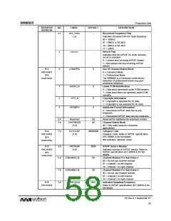
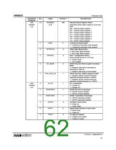
R30
PWRDN
1Eh
0
1
2
3
4
5
PLLPD
SPDIFRXPD
SPDIFTXPD
OSCPD
1
1
1
0
0
0
PLL Powerdown
0 = Enable PLL
1 = Disable PLL
S/PDIF Receiver Powerdown
0 = S/PDIF receiver enabled
1 = S/PDIF receiver disabled
S/PDIF Transmitter Powerdown
0 = S/PDIF transmitter enabled
1 = S/PDIF transmitter disabled
Oscillator Power Down
0 = Power Up
1 = Power Down
AIFPD
Digital Audio Interface Power Down
1= Power Down
0 = Power Up
TRIOP
Tri-state all Outputs
0 = Outputs not tri-stated
1 = Outputs tri-stated
PD Rev 4.1 September 07
62
w

 WOLFSON [ WOLFSON MICROELECTRONICS PLC ]