Production Data
WM8805
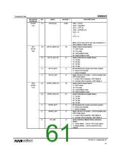
REGISTER
ADDRESS
BIT
LABEL
DEFAULT
DESCRIPTION
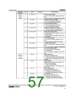
GPO67
1Ah
7:4
GPO7[3:0]
0100
1001 = CSUD
1010 = DEEMPH
1011 = CPY_N
1100 = ZEROFLAG
1101 = 0
↓
1111 = 0
Note: GPO2 and GPO7 are only available in 2-
wire software control mode.
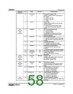
R27
AIFTX
1Bh
1:0
3:2
AIFTX_FMT[1:0]
AIFTX_WL[1:0]
10
01
Audio Data Format Select
11: DSP mode
10: I2S mode
01: Left justified mode
00: Right justified mode
Audio Data Word Length Select
11: 24 bits
10: 24 bits
01: 20 bits
00: 16 bits
4
5
AIFTX_BCP
AIFTX_LRP
0
0
BCLK Invert (for master and slave modes)
0 = BCLK not inverted
1 = BCLK inverted
Right, left and I2S modes – LRCLK polarity and
DSP mode select
1 = invert LRCLK polarity / DSP Mode B
0 = normal LRCLK polarity / DSP Mode A
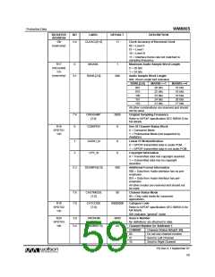
Audio Data Format Select
11: DSP mode
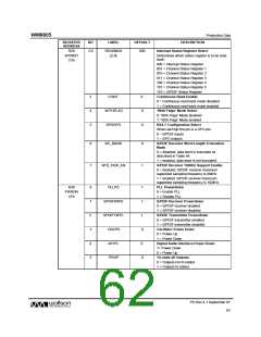
R28
AIFRX
1Ch
1:0
3:2
AIFRX_FMT[1:0]
AIFRX_WL[1:0]
10
01
10: I2S mode
01: Left justified mode
00: Right justified mode
Audio Data Word Length Select
11: 24 bits
10: 24 bits
01: 20 bits
00: 16 bits
4
5
AIFRX_BCP
AIFRX_LRP
0
0
BCLK Invert (for master and slave modes)
0 = BCLK not inverted
1 = BCLK inverted
Right, left and I2S modes – LRCLK polarity and
DSP mode select
1 = invert LRCLK polarity / DSP Mode B
0 = normal LRCLK polarity / DSP Mode A
6
AIF_MS
0
Audio Interface Master/Slave Interface
Select
0 = Slave Mode – LRCLK, BCLK are inputs
1= Master Mode – LRCLK and BCLK are
outputs
PD Rev 4.1 September 07
61
w

 WOLFSON [ WOLFSON MICROELECTRONICS PLC ]