Production Data
WM8524
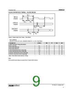
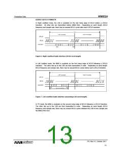
AUDIO INTERFACE TIMING – SLAVE MODE
tBCY
BCLK
(input)
VIH
VIL
tBCH
tBCL
LRCLK
(input)
VIH
VIL
tLRH
tLRSU
DACDAT
(input)
VIH
VIL
tDS
tDH
Figure 2 Digital Audio Data Timing – Slave Mode
Test Conditions
LINEVDD=AVDD=2.97~3.63V, LINEGND=AGND=0V, TA=+25°C, Slave Mode
PARAMETER
SYMBOL
MIN
TYP
MAX
UNIT
Audio Data Input Timing Information
BCLK cycle time
tBCY
tBCH
tBCL
tLRSU
tLRH
tDH
27
11
11
7
ns
ns
ns
ns
ns
ns
ns
BCLK pulse width high
BCLK pulse width low
LRCLK set-up time to BCLK rising edge
LRCLK hold time from BCLK rising edge
DACDAT hold time from LRCLK rising edge
DACDAT set-up time to BCLK rising edge
5
5
tDS
7
Table 1 Slave Mode Audio Interface Timing
Note:
BCLK period should always be greater than or equal to MCLK period.
PD, Rev 4.1, October 2011
9
w

 WOLFSON [ WOLFSON MICROELECTRONICS PLC ]