WM8524
Production Data
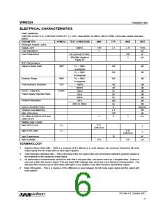
ELECTRICAL CHARACTERISTICS
Test Conditions
LINEVDD=AVDD=3.3V, LINEGND=AGND=0V, TA=+25°C, Slave Mode, fs=48kHz, MCLK=256fs, 24-bit data, unless otherwise
stated.
PARAMETER
SYMBOL
TEST CONDITIONS
MIN
TYP
MAX
UNIT
Analogue Output Levels
Output Level
0dBFS
1.89
1
2.1
2.31
Vrms
kΩ
Load Impedance
Load Capacitance
No external RC filter
300
1
pF
With filter shown in
Figure 16
µF
DAC Performance
Signal to Noise Ratio
SNR
RL = 10kΩ
A-weighted
RL = 10kΩ
Un-weighted
RL = 10kΩ
A-weighted
-1dBFS
106
104
104
dB
dB
dB
Dynamic Range
DNR
THD
Total Harmonic Distortion
-89
-86
54
dB
dB
0dBFS
AVDD + LINEVDD
PSRR
100Hz
dB
Power Supply Rejection Ratio
1kHz
54
dB
20kHz
50
dB
Channel Separation
1kHz
dB
100
20Hz to 20kHz
dB
95
0
System Absolute Phase
Channel Level Matching
Mute Attenuation
degrees
dB
0.1
-120
0
dB
DC Offset at LINEVOUTL and
LINEVOUTR
-1
1
mV
Digital Logic Levels
Input HIGH Level
VIH
VIL
0.7
LINEVDD
V
V
Input LOW Level
0.3
LINEVDD
Input Capacitance
Input Leakage
10
pF
-0.9
0.9
A
TERMINOLOGY
1. Signal-to-Noise Ratio (dB) – SNR is a measure of the difference in level between the maximum theoretical full scale
output signal and the output with no input signal applied.
2. Total Harmonic Distortion (dB) – THD is the level of the rms value of the sum of harmonic distortion products relative to
the amplitude of the measured output signal.
3. All performance measurements carried out with 20kHz low pass filter, and where noted an A-weighted filter. Failure to
use such a filter will result in higher THD and lower SNR readings than are found in the Electrical Characteristics. The
low pass filter removes out of band noise; although it is not audible it may affect dynamic specification values.
4. Mute Attenuation – This is a measure of the difference in level between the full scale output signal and the output with
mute applied.
PD, Rev 4.1, October 2011
w
6

 WOLFSON [ WOLFSON MICROELECTRONICS PLC ]