WM8352
Production Data
The current time can be read from the registers defined above. As the content of the time registers
changes every second, a single register read, executed at an arbitrary time, does not guarantee an
accurate time reading. Two possible methods are recommended for reliable reading of the time
registers:
.
Read after interrupt: the RTC_SEC interrupt (see Section 22.5) indicates that the seconds
counter has just been incremented, and that the RTC registers will not change again within
the next 999ms. A register read executed immediately after an RTC_SEC interrupt can
therefore be taken as an accurate time reading.
.
Two consecutive reads: if two consecutive reads within a short time (less than 1s apart)
return the same result, this can be taken as an accurate reading. If the two results differ,
the procedure should be repeated.
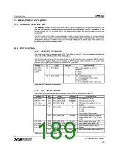
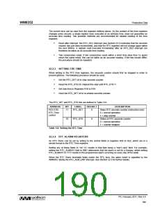
22.2.3 SETTING THE TIME
When writing to the RTC time registers, the seconds counter should first be stopped in order to
prevent glitches. The following procedure should be used:
.
.
.
.
Set the RTC_SET bit to stop seconds counter
Read the RTC_STS bit. Repeat this step until RTC_STS=1
Set new time in Registers R16 to R19
Clear the RTC_SET bit to re-enable seconds counter.
The RTC_SET and RTC_STS bits are defined in Table 132.
ADDRESS
BIT
LABEL
DEFAULT
DESCRIPTION
Stops RTC seconds counter (instruction only)
0 = normal operation
R23 (17h)
11
RTC_SET
0
RTC Time
control
1 = stop counter
10
RTC_STS
0
Status of RTC seconds counter
0 = normal operation
1 = counter stopped
Table 132 Setting the RTC Time
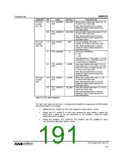
22.2.4 RTC ALARM REGISTERS
An RTC Alarm can be set by writing to the control fields in registers R20 to R22, which are in a
similar format to the RTC Time registers.
Setting any of these fields to “All 1’s” results in that field being a “don’t care” field. For example,
setting the RTC_ALMDAY field to 0001 determines that the alarm is set for a Sunday, whilst setting
RTC_ALMDAY to 1111 results in the programmed alarm occurring on every day of the week.
When the RTC Alarm time/date fields match the RTC time, the alarm event is signalled by the
WM8352 raising the RTC_ALM_EINT interrupt. See Section 22.5 for further details.
PD, February 2011, Rev 4.4
190
w

 WOLFSON [ WOLFSON MICROELECTRONICS PLC ]