Production Data
WM8325
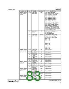
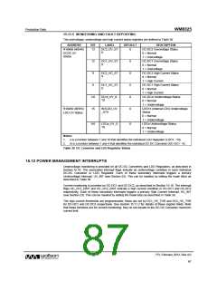
15.11.5 MONITORING AND FAULT REPORTING
The overvoltage, undervoltage and high current status registers are defined in Table 38.
ADDRESS
BIT
LABEL
DEFAULT
DESCRIPTION
R16468 (4054h)
DC2_OV_ST
S
DC-DC2 Overvoltage Status
0 = Normal
13
0
DCDC UV
Status
1 = Overvoltage
DC1_OV_ST
S
DC-DC1 Overvoltage Status
0 = Normal
12
9
0
0
0
0
0
1 = Overvoltage
DC2_HC_ST
S
DC-DC2 High Current Status
0 = Normal
1 = High Current
8
DC1_HC_ST
S
DC-DC1 High Current Status
0 = Normal
1 = High Current
DCm_UV_S
TS
DC-DCm Undervoltage Status
0 = Normal
3:0
15
1 = Undervoltage
R16469 (4055h)
LDO UV Status
INTLDO_UV
_STS
LDO13 (Internal LDO) Undervoltage
Status
0 = Normal
1 = Undervoltage
LDOn Undervoltage Status
0 = Normal
9:0
LDOn_UV_S
TS
0
1 = Undervoltage
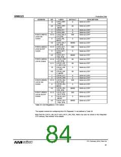
Notes:
1. n is a number between 1 and 10 that identifies the individual LDO Regulator (LDO1 - 10).
2. m is a number between 1 and 4 that identifies the individual DC-DC Converter (DC-DC1 - 4).
Table 38 DC Converter and LDO Regulator Status
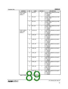
15.12 POWER MANAGEMENT INTERRUPTS
Undervoltage monitoring is provided on all DC-DC Converters and LDO Regulators, as described in
Section 15.10. The associated interrupt flags indicate an undervoltage condition in each individual
DC-DC Converter or LDO Regulator. Each of these secondary interrupts triggers a primary
Undervoltage Interrupt, UV_INT (see Section 23). This can be masked by setting the mask bit(s) as
described in Table 39.
Current monitoring is provided on DC-DC1 and DC-DC2, as described in Section 15.10. The interrupt
flags HC_DC1_EINT and HC_DC2_EINT indicate a high current condition in DC-DC1 and DC-DC2
respectively. Each of these secondary interrupts triggers a primary High Current Interrupt, HC_INT
(see Section 23). This can be masked by setting the mask bit(s) as described in Table 39.
The high current thresholds are programmable; these are set by DC1_HC_THR and DC2_HC_THR
for DC-DC1 and DC-DC2 respectively. See Section 15.11.2 for details of these register fields. Note
that these functions are for current monitoring; they do not equate to the DC-DC Converter maximum
current limit.
PD, February 2012, Rev 4.0
87
w

 WOLFSON [ WOLFSON MICROELECTRONICS PLC ]