WM8325
Production Data
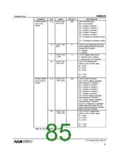
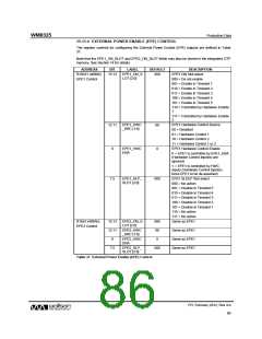
15.11.4 EXTERNAL POWER ENABLE (EPE) CONTROL
The register controls for configuring the External Power Enable (EPE) outputs are defined in Table
37.
Note that the EPE1_ON_SLOT and EPE2_ON_SLOT fields may also be stored in the integrated OTP
memory. See Section 14 for details.
ADDRESS
R16521 (4089h)
EPE1 Control
BIT
LABEL
DEFAULT
DESCRIPTION
EPE1 ON Slot select
15:13
EPE1_ON_S
LOT [2:0]
000
000 = Do not enable
001 = Enable in Timeslot 1
010 = Enable in Timeslot 2
011 = Enable in Timeslot 3
100 = Enable in Timeslot 4
101 = Enable in Timeslot 5
110 = Controlled by Hardware Enable
1
111 = Controlled by Hardware Enable
2
EPE1_HWC
_SRC [1:0]
EPE1 Hardware Control Source
00 = Disabled
12:11
00
01 = Hardware Control 1
10 = Hardware Control 2
11 = Hardware Control 1 or 2
EPE1 Hardware Control Enable
EPE1_HWC
ENA
8
0
0 = EPE1 is controlled by EPE1_ENA
(Hardware Control input(s) are
ignored)
1 = EPE1 is controlled by HWC
inputs (Hardware Control input(s)
force EPE1 to be de-asserted)
EPE1_SLP_
SLOT [2:0]
EPE1 SLEEP Slot select
000 = No action
7:5
000
001 = Disable in Timeslot 5
010 = Disable in Timeslot 4
011 = Disable in Timeslot 3
100 = Disable in Timeslot 2
101 = Disable in Timeslot 1
110 = No action
111 = No action
R1652 (408Ah)
EPE2 Control
EPE2_ON_S
LOT [2:0]
Same as EPE1
15:13
12:11
8
000
00
EPE2_HWC
_SRC [1:0]
Same as EPE1
Same as EPE1
Same as EPE1
EPE2_HWC
ENA
0
EPE2_SLP_
SLOT [2:0]
7:5
000
Table 37 External Power Enable (EPE) Control
PD, February 2012, Rev 4.0
86
w

 WOLFSON [ WOLFSON MICROELECTRONICS PLC ]