WM8325
Production Data
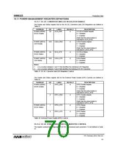
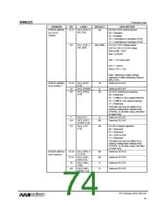
15.11 POWER MANAGEMENT REGISTER DEFINITIONS
15.11.1 DC-DC CONVERTER AND LDO REGULATOR ENABLE
The Enable and Status register bits for the DC-DC Converters and LDO Regulators are defined in
Table 31.
ADDRESS
R16464 (4050h)
DCDC Enable
BIT
LABEL
DEFAULT
DESCRIPTION
DC-DCm Enable request
0 = Disabled
DCm_ENA
3:0
0
1 = Enabled
(Note that the actual status is
indicated in DCm_STS)
R16465 (4051h)
LDO Enable
LDOn_ENA
LDOn Enable request
0 = Disabled
10:0
0
1 = Enabled
(Note that the actual status is
indicated in LDOn_STS)
R16466 (4052h)
DCDC Status
DCm_STS
LDOn_STS
DC-DCm Status
0 = Disabled
1 = Enabled
LDOn Status
0 = Disabled
1 = Enabled
3:0
0
0
R16467 (4053h)
LDO Status
10:0
Notes:
1. n is a number between 1 and 11 that identifies the individual LDO Regulator.
2. m is a number between 1 and 4 that identifies the individual DC-DC Converter.
Table 31 DC-DC Converter and LDO Regulator Control
The Enable and Status register bits for the External Power Enable (EPE) Controls are defined in
Table 32.
ADDRESS
R16464 (4050h)
DCDC Enable
BIT
LABEL
DEFAULT
DESCRIPTION
EPE2 Enable request
EPE2_ENA
7
0
0 = Disabled
1 = Enabled
(Note that the actual status is
indicated in EPE2_STS)
EPE1_ENA
EPE1 Enable request
0 = Disabled
6
0
1 = Enabled
(Note that the actual status is
indicated in EPE1_STS)
R16466 (4052h)
DCDC Status
EPE2_STS
EPE1_STS
EPE2 Status
0 = Disabled
1 = Enabled
EPE1 Status
0 = Disabled
1 = Enabled
7
6
0
0
Table 32 External Power Enable (EPE) Control
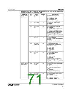
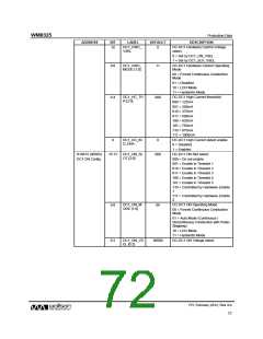
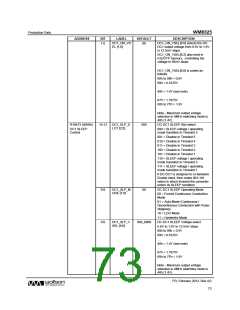
15.11.2 DC-DC SYNCHRONOUS BUCK CONVERTER CONTROL
The register controls for configuring the DC-DC synchronous buck converters 1-4 are defined in Table
33.
PD, February 2012, Rev 4.0
70
w

 WOLFSON [ WOLFSON MICROELECTRONICS PLC ]