Production Data
WM8321
REGISTER
ADDRESS
BIT
LABEL
DEFAULT
DESCRIPTION
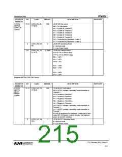
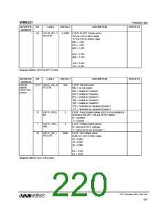
LDO10 ON Slot select
REFER TO
R16516
(4084h)
LDO10 ON
Control
LDO10_ON_SL
OT [2:0]
15:13
000
000 = Do not enable
001 = Enable in Timeslot 1
010 = Enable in Timeslot 2
011 = Enable in Timeslot 3
100 = Enable in Timeslot 4
101 = Enable in Timeslot 5
110 = Controlled by Hardware Enable 1
111 = Controlled by Hardware Enable 2
LDO10 ON Operating Mode
0 = Normal mode
LDO10_ON_M
ODE
8
0
1 = Low Power mode
LDO10 ON Voltage select
1.0V to 1.6V in 50mV steps
1.7V to 3.5V in 100mV steps
00h = 1.00V
LDO10_ON_V
SEL [4:0]
4:0
0_0000
01h = 1.05V
02h = 1.10V
…
0Ch = 1.60V
0Dh = 1.70V
…
1Eh = 3.40V
1Fh = 3.50V
Register 4084h LDO10 ON Control
REGISTER
ADDRESS
BIT
LABEL
DEFAULT
DESCRIPTION
REFER TO
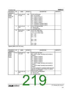
R16517
(4085h)
LDO10
SLEEP
Control
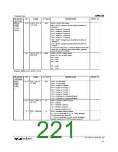
LDO10_SLP_S
LOT [2:0]
LDO10 SLEEP Slot select
15:13
000
000 = SLEEP voltage / operating mode transition in
Timeslot 5
001 = Disable in Timeslot 5
010 = Disable in Timeslot 4
011 = Disable in Timeslot 3
100 = Disable in Timeslot 2
101 = Disable in Timeslot 1
110 = SLEEP voltage / operating mode transition in
Timeslot 3
111 = SLEEP voltage / operating mode transition in
Timeslot 1
If LDO10 is assigned to a Hardware Enable Input, then
codes 001-101 select in which timeslot the regulator
enters its SLEEP condition.
LDO10_SLP_M
ODE
LDO10 SLEEP Operating Mode
0 = Normal mode
8
1
1 = Low Power mode
PD, February 2012, Rev 4.0
219
w

 WOLFSON [ WOLFSON MICROELECTRONICS PLC ]