Production Data
WM8321
REGISTER
ADDRESS
BIT
LABEL
DEFAULT
DESCRIPTION
or under HWC modes.
REFER TO
Register 4068h LDO1 Control
REGISTER
ADDRESS
BIT
LABEL
DEFAULT
DESCRIPTION
REFER TO
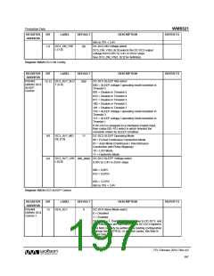
R16489
(4069h)
LDO1 ON
Control
LDO1_ON_SL
OT [2:0]
LDO1 ON Slot select
000 = Do not enable
15:13
000
001 = Enable in Timeslot 1
010 = Enable in Timeslot 2
011 = Enable in Timeslot 3
100 = Enable in Timeslot 4
101 = Enable in Timeslot 5
110 = Controlled by Hardware Enable 1
111 = Controlled by Hardware Enable 2
LDO1 ON Operating Mode
0 = Normal mode
LDO1_ON_MO
DE
8
0
1 = Low Power mode
LDO1_ON_VS
EL [4:0]
LDO1 ON Voltage select
4:0
0_0000
0.9V to 1.6V in 50mV steps
1.7V to 3.3V in 100mV steps
00h = 0.90V
01h = 0.95V
…
0Eh = 1.60V
0Fh = 1.70V
…
1Eh = 3.20V
1Fh = 3.30V
Register 4069h LDO1 ON Control
REGISTER
ADDRESS
BIT
LABEL
DEFAULT
DESCRIPTION
REFER TO
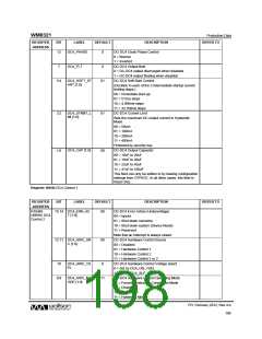
R16490
(406Ah)
LDO1
SLEEP
Control
LDO1_SLP_SL
OT [2:0]
LDO1 SLEEP Slot select
15:13
000
000 = SLEEP voltage / operating mode transition in
Timeslot 5
001 = Disable in Timeslot 5
010 = Disable in Timeslot 4
011 = Disable in Timeslot 3
100 = Disable in Timeslot 2
101 = Disable in Timeslot 1
110 = SLEEP voltage / operating mode transition in
Timeslot 3
111 = SLEEP voltage / operating mode transition in
Timeslot 1
If LDO1 is assigned to a Hardware Enable Input, then
codes 001-101 select in which timeslot the regulator
enters its SLEEP condition.
LDO1_SLP_M
ODE
LDO1 SLEEP Operating Mode
0 = Normal mode
8
1
1 = Low Power mode
PD, February 2012, Rev 4.0
201
w

 WOLFSON [ WOLFSON MICROELECTRONICS PLC ]