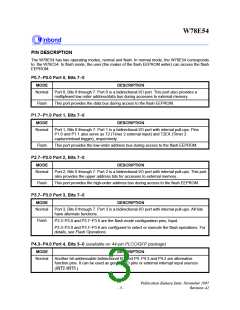
W78E54
FUNCTIONAL DESCRIPTION
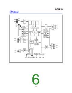
The W78E54 architecture consists of a core controller surrounded by various registers, five general
purpose I/O ports, 256 bytes of RAM, three timer/counters, and a serial port. The processor supports
111 different opcodes and references both a 64K program address space and a 64K data storage
space.
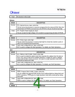
Timers 0, 1, and 2
Timers 0, 1, and 2 each consist of two 8-bit data registers. These are called TL0 and TH0 for Timer 0,
TL1 and TH1 for Timer 1, and TL2 and TH2 for Timer 2. The TCON and TMOD registers provide
control functions for timers 0 and 1. The T2CON register provides control functions for Timer 2.
RCAP2H and RCAP2L are used as reload/capture registers for Timer 2.
The operations of Timer 0 and Timer 1 are the same as in the W78C51. Timer 2 is a special feature
of the W78E54: it is a 16-bit timer/counter that is configured and controlled by the T2CON register.
Like Timers 0 and 1, Timer 2 can operate as either an external event counter or as an internal timer,
depending on the setting of bit C/T2 in T2CON. Timer 2 has three operating modes: capture, auto-
reload, and baud rate generator. The clock speed at capture or auto-reload mode is the same as that
of Timers 0 and 1.
Clock
The W78E54 is designed to be used with either a crystal oscillator or an external clock. Internally, the
clock is divided by two before it is used. This makes the W78E54 relatively insensitive to duty cycle
variations in the clock.
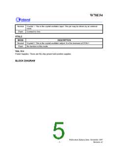
Crystal Oscillator
The W78E54 incorporates a built-in crystal oscillator. To make the oscillator work, a crystal must be
connected across pins XTAL1 and XTAL2. In addition, a load capacitor must be connected from each
pin to ground, and a resistor must also be connected from XTAL1 to XTAL2 to provide a DC bias
when the crystal frequency is above 24 MHz.
External Clock
An external clock should be connected to pin XTAL1. Pin XTAL2 should be left unconnected. The
XTAL1 input is a CMOS-type input, as required by the crystal oscillator. As a result, the external clock
signal should have an input one level of greater than 3.5 volts.
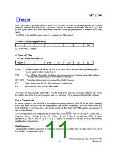
Power Management
Idle Mode
The idle mode is entered by setting the IDL bit in the PCON register. In the idle mode, the internal
clock to the processor is stopped. The peripherals and the interrupt logic continue to be clocked. The
processor will exit idle mode when either an interrupt or a reset occurs.
Power-down Mode
Publication Release Date: November 1997
- 7 -
Revision A2

 WINBOND [ WINBOND ]