Preliminary W78E378/W78C378/W78C374
Parabola Interrupt Generator
The parabola interrupt generator is a 13-bit auto-reload timer, which generates an interrupt to the
CPU periodically for software to load the parabola waveform data to the dynamic DACs
-
(DAC8 DAC10). The software should calculate the value of the PARAH and PARAL registers by:
´
¸
segment number. The segment number is the number of integration segments
(Vcount
16)
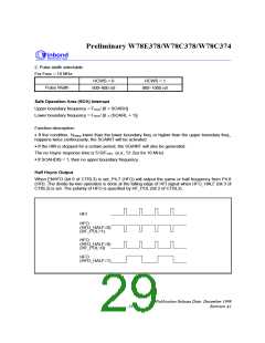
between two Vsync pulses. The interrupt interval is programmable:
·
·
·
Time base = 1/Fosc
Programmable interrupt period = Time base (PARAH 256 + PARAL + 1)
´
´
´
Maximum period = Time base 8192
Note: Zero value in [PARAH, PARAL] is inhibited.
A-to-D Converter
(ref. Application Note in Appendix A.)
One 4-bit Analog-to-Digital Converter.
· Conversion time = (6/Fosc) ´ 128 sec.
· 7 channels selected by an analog multiplexer
(ADCS2, ADCS1, ADCS0) (0, 0, 0) (0, 0, 1) (0, 1, 0) (0, 1, 1) (1, 0, 0) (1, 0, 1) (1, 1, 0)
Selected Channel
ADC0
ADC1
ADC2
ADC3
ADC4
ADC5
ADC6
The conversion of the ADC is started by setting bit ADCSTRT in CTRL1 by software. When the
conversion is completed, the ADCSTRT bit is cleared by hardware automatically, and the ADCINT bit
in INTVECT is set by hardware at the same time if MADCINT in INTMSK is set.
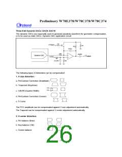
PWM DACs
Eight 8-bit Static DACs: DAC0-DAC7
PWM
·
·
·
The PWM frequency F
= Fosc ÷ 255
The duty cycle of the PWM output = Register value ÷ 255
CC
´
The DC voltage after the low pass filter = V
duty cycle
Static DAC application circuit:
Low-pass filter
VOUTPUT
Static DAC
R
C
T = RC
¡ Ñ
VOUTPUT = VCC n/255, if T >> T PWM
Publication Release Date: December 1999
Revision A1
- 25 -

 WINBOND [ WINBOND ]