W78C32C/W78C032C
9. PACKAGE DIMENSIONS
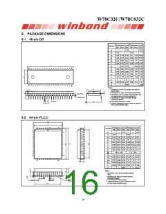
9.1 40-pin DIP
Dimension in inchDimension in mm
Symbol
Min. Nom. Max. Min. Nom. Max.
5.334
0.210
A
A
A
B
B
c
0.010
0.150 0.155 0.160 3.81
0.254
1
2
3.937 4.064
0.016 0.018
0.406 0.457 0.559
1.219 1.27 1.372
0.022
0.054
0.050
0.048
0.008
1
0.010 0.014 0.203 0.254 0.356
D
2.055 2.070
52.58
15.494
13.97
52.20
15.24
D
E
40
21
0.610
0.590 0.600
14.986
13.72 13.84
0.540
0.545
0.550
0.110
E
e
L
a
1
0.090 0.100
0.120 0.130
0
2.286 2.54 2.794
1
0.140 3.048 3.302
3.556
15
1
E
15
0
17.01
2.286
0.630 0.650 0.670 16.00 16.51
0.090
e
A
S
1
20
Notes:
E
1. Dimension D Max. & S include mold flash or
tie bar burrs.
S
c
2. Dimension E1 does not include interlead flash.
3. Dimension D & E1 include mold mismatch and
are determined at the mold parting line.
A2
A
L
Base Plane
1
A
.
Seating Plane
4. Dimension B1 does not include dambar
protrusion/intrusion.
B
e1
eA
5. Controlling dimension: Inches.
6. General appearance spec. should be based on
final visual inspection spec.
a
B1
9.2 44-pin PLCC
HD
D
1
6
44
40
Dimension in inch Dimension in mm
Symbol
Nom.
Nom.
Min.
Max. Min.
Max.
7
39
0.185
4.699
A
A
A2
b
b
c
0.020
0.508
1
0.145 0.150
0.026 0.028
3.683 3.81 3.937
0.155
0.032 0.66
0.813
0.559
0.356
0.711
0.457
1
0.406
0.022
0.016 0.018
HE
GE
E
0.008 0.010 0.014 0.203 0.254
16.46 16.59 16.71
16.46 16.59 16.71
1.27 BSC
0.648 0.653 0.658
D
E
e
0.648 0.653
0.658
0.050 BSC
0.590
0.590
0.680
0.680
0.090
14.99 15.49 16.00
14.99 15.49 16.00
17.27 17.53 17.78
17.27 17.53 17.78
17
29
0.610
0.630
GD
0.610 0.630
0.690 0.700
0.690 0.700
0.100
G
E
18
28
H
D
c
H
L
y
E
2.54
2.794
0.10
0.110 2.296
0.004
L
Notes:
A2
A1
A
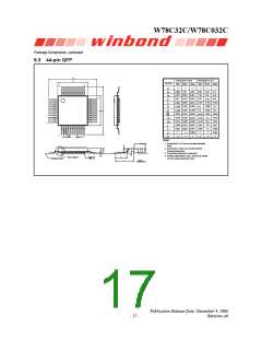
1. Dimension D & E do not include interlead
flash.
2. Dimension b1 does not include dambar
protrusion/intrusion.
θ
e
b
3. Controlling dimension: Inches
4. General appearance spec. should be based
on final visual inspection spec.
b1
Seating Plane
y
GD
- 16 -

 WINBOND [ WINBOND ]