W25Q20BW
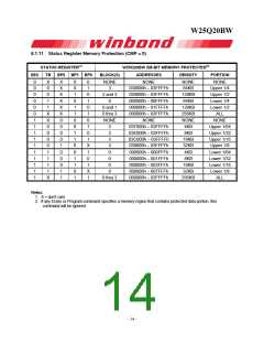
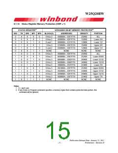
8.1.6 Complement Protect (CMP)
The Complement Protect bit (CMP) is a non-volatile read/write bit in the status register (S14). It is used in
conjunction with SEC, TB, BP2, BP1 and BP0 bits to provide more flexibility for the array protection. Once
CMP is set to 1, previous array protection set by SEC, TB, BP2, BP1 and BP0 will be reversed. For
instance, when CMP=0, a top 4KB sector can be protected while the rest of the array is not; when
CMP=1, the top 4KB sector will become unprotected while the rest of the array become read-only. Please
refer to the Status Register Memory Protection table for details. The default setting is CMP=0.
8.1.7 Status Register Protect (SRP1, SRP0)
The Status Register Protect bits (SRP1 and SRP0) are non-volatile read/write bits in the status register
(S8 and S7). The SRP bits control the method of write protection: software protection, hardware
protection, power supply lock-down or one time programmable (OTP) protection.
Status
Register
SRP1 SRP0 /WP
Description
Software
Protection
/WP pin has no control. The Status register can be written to
after a Write Enable instruction, WEL=1. [Factory Default]
0
0
0
1
0
1
1
0
1
X
0
Hardware
Protected
When /WP pin is low the Status Register locked and can not
be written to.
Hardware
When /WP pin is high the Status register is unlocked and can
1
Unprotected be written to after a Write Enable instruction, WEL=1.
Power Supply Status Register is protected and can not be written to again
Lock-Down
X
X
until the next power-down, power-up cycle.(1)
One Time
Program(2)
Status Register is permanently protected and can not be
written to.
1
Note:
1. When SRP1, SRP0 = (1, 0), a power-down, power-up cycle will change SRP1, SRP0 to (0, 0) state.
2. This feature is available upon special order. Please contact Winbond for details.
8.1.8 Erase/Program Suspend Status (SUS)
The Suspend Status bit is a read only bit in the status register (S15) that is set to 1 after executing a
Erase/Program Suspend (75h) instruction. The SUS status bit is cleared to 0 by Erase/Program Resume
(7Ah) instruction as well as a power-down, power-up cycle.
8.1.9 Security Register Lock Bits (LB3, LB2, LB1, LB0)
The Security Register Lock Bits (LB3, LB2, LB1, LB0) are non-volatile One Time Program (OTP) bits in
Status Register (S13, S12, S11, S10) that provide the write protect control and status to the Security
Registers. The default state of LB3-0 is 0, Security Registers are unlocked. LB3-0 can be set to 1
individually using the Write Status Register instruction. LB3-0 are One Time Programmable (OTP), once
it’s set to 1, the corresponding 256-Byte Security Register will become read-only permanently.
- 12 -

 WINBOND [ WINBOND ]