Component Carriers and Housings
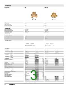
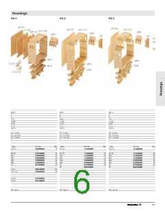
Weidmüller DK 4 and DKT 4 terminals Weidmüller EG 4 housing
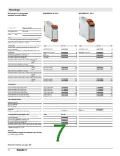
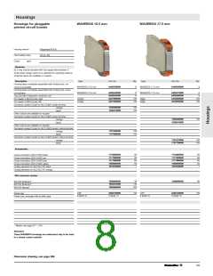
Weidmüller housings type WAVEBOX
are suitable for the installation of electronic as type EG 3, offers the same width of
It is essential to provide fit-for-use housings
components with a maximum diameter or
22.5 mm. However, the greater installation for modern electronic components. Setting
width of 4.5 mm. Four independent clamp- depth (75 mm) and height (109 mm) allow and control functions must be easily car-
ing yoke screw connections are available.
A snap-on frame expands the installation
space in the DK4 by 6 mm respectively.
Depending on type, these modular termi-
nals are suitable for mounting on TS 32,
TS 35 x 7.5 or TS 35 x 15 mounting rails
according to European standards EN 50
035 and EN 50 022.
the installation of more complex circuit
configurations. The built-in installation can respect to heat dissipation and EMV prop-
be connected via 6 screw connections.
The snap-on combination foot allows the
terminal to be mounted on TS 32, TS 35 x costs in the switchgear cabinet.
7.5 or TS 35 x 15 mounting rails. Due to In addition, ergonomics and design are
the sliding foot construction, the EG 4 can becoming increasingly important for high-
be slid forwards or backwards on the
locking foot, and can be turned through
180° (e.g. exchanging of input and out-
put).
ried out and technical requirements with
erties should be supported.
An ideal design saves space and wiring
quality electronic products.
These are the criteria that led to the devel-
opment of WAVEBOX. Simplified produc-
tion methods (shaft soldering, SMD) ensure
cost-savings for the customer.
The WAVEBOX is characterised by:
• Optimum width for any application
(12.5 mm, 17.5 mm, 22.5 mm)
• Large component assembly surface;
SMDs can be mounted on the solder
side
• UL94 flammability class V2
• No tools required for assembly
• Plug-in printed circuit board
• Plug-in cross-connection via ZQV 2.5 N
• Hinged, transparent cover
• BLZ 5.08 screw/plug and socket con-
nector
• BLFZ 5.08 optional tension clamp/plug
and socket connector
• Marking option with WS tags
• Mounts onto TS 35
Weidmüller individual parts for RS 70
locking socket
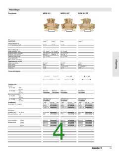
Weidmüller WDK 2.5 terminals
are suitable for the installation of electrical
components with a maximum width of 4
mm. As many as four independent clamp-
ing yoke screw connections or 4 6.3 x 0.8 correspond to type EG 4. The EG 5 has
tab connections are available. These termi- 12 screw connections, which can be wired
nals are suitable for mounting on TS 35 x
7.5 or TS 35 x 15 mounting rails.
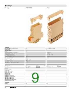
Weidmüller EG 5 housings
with solder lugs inside the housing. The
snap-on combination foot allows the ter-
minal to be mounted on TS 32, TS 35 x
7.5 or TS 35 x 15 mounting rails. Due to
the sliding foot construction, the EG 4 can
be slid 6 mm forwards or backwards on
the engaging foot and can be turned
through 180° (e.g. exchanging input and
output).
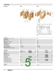
Weidmüller EG 1 housings
offer 4 screw connections and, as acces-
sories, up to 4 0.8 x 4.8 mm solder/tab
connections on a width of 18 mm. The
screw clamp busbar ends with a solder
ring inside the housing. Two end plates
seal the module. Depending on type, the
modules are mounted on TS 32, TS 35 x
7.5 or TS 35 x 15 mounting rails.
Weidmüller EG 6 housings
have a bus-suitable contact carrier. The
bus connection is created by directly
mounting several housings in a row. 32
connections are available on both sides of
the housing as crimp connector block
contacts. The housing accepts printed cir-
cuit boards with dimensions of 100x120
mm. The printed circuit board is adapted
with a VG 64 DIN strip. The front panel is
screwed onto the circuit board similar to
the 19" technology. The locking foot
allows easy mounting onto the TS 35
mounting rail.
Weidmüller EG 2 housings
latch together to form units from 20 mm in
width. Any desired intermediate parts or
feet can be connected between two side
pieces (locking feet) at intervals of 5 mm. In
this way, a carrier module is constructed
for PCB, on which various components
can be soldered. The assembly snaps onto
TS 32, TS 35 x 7.5 or TS 35 x 15 mount-
ing rails.
The external shape of these housings cor-
responds to Type EG 1. Four screw con-
nections or up to 8 0.8 x 6.6 mm/0.8 x
2.8 mm tab connectors are connected
with a printed circuit board in the housing.
They can be mounted on TS 32, TS 35 x
7.5 or TS 35 x 15 mounting rails.
Weidmüller EG 3 housings
The Weidmüller RSX custom circuit
module
provides 6 screw connections or 12
0.8 x 6.3 mm/0.8 x 2.8 mm tab connec-
tions on a width of 22.5 mm. As an acces-
sory, Weidmüller offers a shaped printed
circuit board with a 2.54 mm hole grid
or fully copper-coated. The engagable
combination foot allows the terminal to
be mounted on TS 32, TS 35 x 7.5
or TS 35 x 15 mounting rails.
The MPL mounting plate is used to mount
the housing directly (without mounting rail).
Due to the sliding foot construction, the
EG 3 can be turned through 180° in all
types of assembly (e.g. exchanging input
and output).
Weidmüller SEG/U housing
is a largely prefabricated unit wich accepts
up to 5 components such as resistors,
diodes, varistors or capacitors via soldering
terminals. The components are connected
via screw clamps or tab connections. This
module is also suitable for mounting on TS
32, TS 35 x 7.5 or TS 35 x 15 mounting
rails.
enable the plug-in module assembly of a
70 x 52 x 1 mm printed circuit board. The
circuit board is attached to the accessory
cover plate via snap-in hooks. The housing
contains a 13-pole socket block for instal-
lation of the module; 6 screw connections
are available for connection. The permissi-
ble power loss in the housing during con-
tinuous operation of terminals in rows
amounts to 1.5W, depending on the sur-
face temperature of the soldered compo-
nents. The snap-on combination foot
allows the housings to be mounted on TS
32, TS 35 x 7.5 or TS 35 x 15 mounting
rails.
Weidmüller locking socket profiles
The RS 45, RS 80 and RS 100 profiles are
available as 2 m long strips. The extruded
profiles can be easily cut to any length with
a saw. In this way, a carrier module is con-
structed for a printed circuit board on
which various components can be solder-
ed. Locking feet can be slid into these pro-
files for mounting on TS 32, TS
35 x 7.5 or TS 35 x 15 mounting rails. The
sliding foot construction of the RS 80 also
allows the fixing foot be turned through 180°.
293

 WEIDMULLER [ WEIDMULLER ]