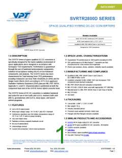
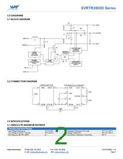
SVRTR2800D Series
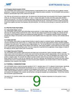
3.2 PERFORMANCE SPECIFICATIONS (CONTINUED)
Tcase = -55 °C to +125 °C, Vin = +28 V ± 5%, Full Load1, Unless Otherwise Specified
SVRTR2815D
5
Parameter
INPUT
Min
Typ
Max
Units
Conditions
7
Voltage
Continuous
18
-
28
-
V
V
40
4
50
Transient, 1 sec
INH < 1.5 V
No Load
Current
-
5
45
50
-
8
90
mA
mA
mApp
V
-
-
Ripple Current
20 Hz to 10 MHz
Turn-On
80
Undervoltage Lockout
14.5
17.5
4
13.0
-
16.5
V
Turn-Off
OUTPUT STATIC
Voltage
+Vout, Tcase = 25 °C
14.85
14.70
14.70
14.55
15
15
15
15
15.15
15.30
15.30
15.45
V
V
V
V
+Vout, Tcase = -55 °C to +125 °C
-Vout, Tcase = 25 °C
-Vout, Tcase = -55 °C to +125 °C
2
Total
0
0
0
0
-
-
-
40
24
W
Power
Either Output
W
2
Total
-
2.67
1.6
60
A
Current
Either Output
-
A
Ripple Voltage
Line Regulation
20 Hz to 10 MHz
25
1
mVpp
mV
mV
mV
mV
+Vout, VIN = 18 V to 40 V
-Vout, VIN = 18 V to 40 V
+Vout, No Load to Full Load
-Vout, No Load to Full Load
+Vout: 60% load, -Vout: 40% load
+Vout: 40% load, -Vout: 60% load
-
20
-
10
1
200
50
8
-
Load Regulation
-
10
200
Cross Regulation, -Vout
-
250
650
mV
4
Load Fault Power Dissipation
-
-
-
-
14
14
W
W
Overload
Short Circuit
OUTPUT DYNAMIC
Load Step, Half to Full Load, Either Output
Output Transient
-
-
-
300
200
600
500
400
mVpk
µs
3
Recovery
4
Output Transient
1200
mVpk
Line Step , Vin = 18V to 40 V
3
-
-
-
300
10
500
20
µs
Recovery
Turn-On, Vin = 0 to 28 V
Delay
ms
Overshoot
20
50
mVpk
FUNCTION
4
Output Inhibited
Output Enabled
0
-
1.5
V
INH Pin Input
4
9
12.5
-
14
V
INH Pin Open Circuit Voltage
SYNC Frequency Range
GENERAL
500
600
kHz
Efficiency
80
84
-
300
550
-
%
4
-
-
µF
kHz
MΩ
g
Capacitive Load
Switching Frequency
Isolation
470
525
500 V DC, Tcase = 25 °C
Non-flanged package option
Flanged package option
100
-
Weight
-
-
-
-
-
52
55
-
g
6
SF, Class K @ Tcase = 55 °C
3.26
MHr
MTBF (MIL-HDBK-217F)
-POST-RAD LIMITS
Input Ripple Current
Output Voltage
-
-
15
15
-
110
15.375
15.550
130
mApp
V
+Vout, Tcase = -55 °C to +125 °C
–Vout, Tcase = -55 °C to +125 °C
14.625
14.450
-
V
Output Ripple Voltage
Switching Frequency
mVpp
kHz
435
-
575
1. Half load at +Vout and half load at -Vout
2. Up to 60% of the total power or current can be drawn from either of the two
outputs.
3. Time for output voltage to settle within 1% of steady-state value
4. Verified by initial electrical design verification. Post design verification,
parameter shall be guaranteed to the limits specified
5. End-of-Life performance includes aging and radiation degradation and is within
standard limits except where noted
6. Correction factor of 0.12 added to ceramic capacitors
7. 37.5 V Max continuous to be compliant to MIL-HDBK-1547 and Aerospace TOR
8. 5% Load to Full Load at -55°C
Sales Information
Phone:(425) 353-3010
Fax: (425) 353-4030
Web: www.vptpower.com
SVRTR2800D - 9.0
Page 4
E-mail: vptsales@vptpower.com

 VPT [ VPT, Inc. ]