MB2S, MB4S & MB6S
Vishay General Semiconductor
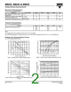
30
25
20
15
T
= 25 °C
J
f = 1 MHz
Vsig = 50mVp-p
10
5.0
0
200
0.1
10
1
Reverse Voltage (V)
100
Figure 5. Typical Junction Capacitance Per Leg
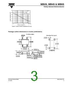
Package outline dimensions in inches (millimeters)
TO-269AA (MBS)
0.029 (0.74)
0.017 (0.43)
Mounting Pad Layout
0.023 MIN.
(0.58 MIN.)
0.161 (4.10)
0.144 (3.65)
0.272 (6.90)
0.252 (6.40)
0.272 MAX.
(6.91 MAX.)
0.030 MIN.
(0.76 MIN.)
0.105 (2.67)
0.095 (2.41)
0.195 (4.95)
0.179 (4.55)
0.205 (5.21)
0.195 (4.95)
0.105(2.67)
0.095(2.41)
o
0-8
0.049 (1.24)
0.106 (2.70)
0.090 (2.30)
0.039 (0.99)
0.062 (1.57)
0.058 (1.47)
0.008 (0.20)
0.004 (0.10) 0.006 (0.15)
0.114 (2.90)
0.110 (2.80)
0.058 (1.47)
0.054 (1.37)
0.016 (0.41)
0.0075 (0.19)
0.0065 (0.16)
0.114 (2.90)
0.094 (2.40)
0.018 (0.46)
0.014 (0.36)
0.038 (0.96)
0.019 (0.48)
Document Number 88661
12-Jul-05
www.vishay.com
3

 VISHAY [ VISHAY ]