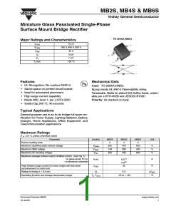
MB2S, MB4S & MB6S
Vishay General Semiconductor
Electrical Characteristics
(TA = 25 °C unless otherwise noted)
Parameter
Test condition
at 0.4 A
Symbol
VF
MB2S
MB4S
1.0
MB6S
Unit
V
Max. instantaneous forward voltage
drop per leg
Maximum DC reverse current at rated TA = 25 °C
IR
5.0
100
µA
pF
DC blocking voltage per leg
TA = 125 °C
Typical junction capacitance per leg
at 4.0 V, 1 MHz
CJ
13
Thermal Characteristics
(TA = 25 °C unless otherwise noted)
Parameter
Symbol
RθJA
RθJA
MB2S
MB4S
MB6S
Unit
85(1)
70(2)
20(1)
Typical thermal resistance per leg
°C/W
RθJL
Notes:
(1) On glass epoxy P.C.B. mounted on 0.05 x 0.05" (1.3 x 1.3 mm) pads
(2) On aluminum substrate P.C.B. with an area of 0.8" x 0.8" (20 x 20 mm) mounted on 0.05 x 0.05" (1.3 x 1.3 mm) solder pad
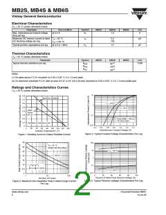
Ratings and Characteristics Curves
(TA = 25 °C unless otherwise noted)
10
0.8
Aluminum Substrate
0.7
T
= 150°C
0.6
0.5
0.4
J
1
0.1
T
= 25 °C
J
Glass
Epoxy
P. C. B .
0.3
0.2
0.1
0
Pulse Width = 300 µs
1% Duty Cycle
Resistive or Inductive Load
0.01
0.2
0.4
0.6
0.8
1.0
1.2
1.4
0
20
40
Ambient Temperature ( °C)
60
80 100 120 140 160
Instantaneous Forward Voltage (V)
Figure 3. Typical Forward Voltage Characteristics Per Leg
Figure 1. Derating Curve for Output Rectified Current
35
100
T
= 40 °C
A
30
25
20
15
10
5.0
0
Single Half Sine-Wave
10
T
J
= 125°C
f = 60 Hz
f = 50 Hz
1
0.1
1 Cycle
T
J
= 25 °C
0.01
0
20
40
60
80
100
1
10
Number of Cycles
100
Percent of Rated Peak Reverse Voltage (%)
Figure 4. Typical Reverse Leakage Characteristics Per Leg
Figure 2. Maximum Non-Repetitive Peak Forward Surge Current
Per Leg
www.vishay.com
2
Document Number 88661
12-Jul-05

 VISHAY [ VISHAY ]