BAS19-V-G, BAS20-V-G, BAS21-V-G
Vishay Semiconductors
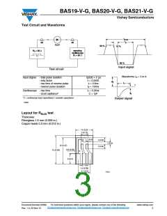
Test Circuit and Waveforms
Ω
Ω
Input signal
Test circuit
Waveforms; IR = 3 m A
Input Signal - total pulse duration
- duty factor
tp(tot) = 2 µs
δ = 0.0025
tr = 0.6ns
- rise time of reverse pulse
- reverse pulse duration
tp = 100ns
Oscilloscope - rise time
tr = 0.35ns
C < 1pF
- cicuit capitance*
*C = oscilloscope input capactitance + parasitic capacitance
Output signal
18098
Layout for R
test
thJA
Thickness:
Fiberglass 1.5 mm (0.059 in.)
Copper leads 0.3 mm (0.012 in.)
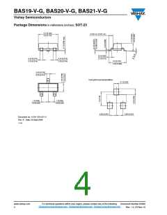
7.5 (0.3)
3 (0.12)
1 (0.4)
2 (0.8)
2 (0.8)
1 (0.4)
12 (0.47)
0.8 (0.03)
15 (0.59)
5 (0.2)
1.5 (0.06)
5.1 (0.2)
17451
Document Number 83390
Rev. 1.0, 23-Nov-10
www.vishay.com
3
For technical questions within your region, please contact one of the following:
DiodesAmericas@vishay.com, DiodesAsia@vishay.com, DiodesEurope@vishay.com

 VISHAY [ VISHAY ]