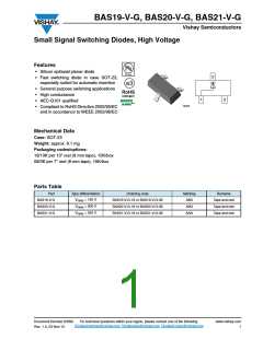
BAS19-V-G, BAS20-V-G, BAS21-V-G
Vishay Semiconductors
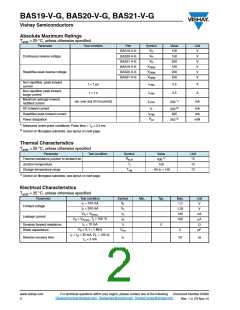
Absolute Maximum Ratings
T
= 25 °C, unless otherwise specified
amb
Parameter
Test condition
Part
Symbol
VR
Value
100
150
200
120
200
250
Unit
V
BAS19-V-G
BAS20-V-G
BAS21-V-G
BAS19-V-G
BAS20-V-G
BAS21-V-G
VR
Continuous reverse voltage
V
VR
V
VRRM
VRRM
VRRM
V
Repetitive peak reverse voltage
V
V
Non-repetitive peak forward
current
IFSM
IFSM
IF(AV)
t = 1 µs
t = 1 s
2.5
0.5
A
A
Non-repetitive peak forward
surge current
Maximum average forward
rectified current
200 1)
(av. over any 20 ms period)
mA
200 2)
625
IF
DC forward current
mA
mA
mW
IFRM
Ptot
Repetitive peak forward current
Power dissipation
250 2)
1) Measured under pulse conditions; Pulse time = Tp ≤ 0.3 ms
2) Device on fiberglass substrate, see layout on next page
Thermal Characteristics
T
= 25 °C, unless otherwise specified
amb
Parameter
Test condition
Symbol
RthJA
Value
430 1)
Unit
Thermal resistance junction to ambient air
Junction temperature
°C
°C
°C
Tj
150
Tstg
Storage temperature range
- 65 to + 150
1) Device on fiberglass substrate, see layout on next page
Electrical Characteristics
T
= 25 °C, unless otherwise specified
amb
Parameter
Test condition
Symbol
VF
Min.
Typ.
Max.
Unit
V
IF = 100 mA
IF = 200 mA
1.0
1.25
100
100
Forward voltage
Leakage current
VF
IR
V
VR = VRmax.
nA
μA
Ω
VR = VRmax., Tj = 150 °C
IF = 10 mA
IR
rf
Dynamic forward resistance
Diode capacitance
5
VR = 0, f = 1 MHz
Ctot
5
pF
IF = IR = 30 mA, RL = 100 Ω,
trr
Reverse recovery time
50
ns
Irr = 3 mA
www.vishay.com
2
Document Number 83390
Rev. 1.0, 23-Nov-10
For technical questions within your region, please contact one of the following:
DiodesAmericas@vishay.com, DiodesAsia@vishay.com, DiodesEurope@vishay.com

 VISHAY [ VISHAY ]