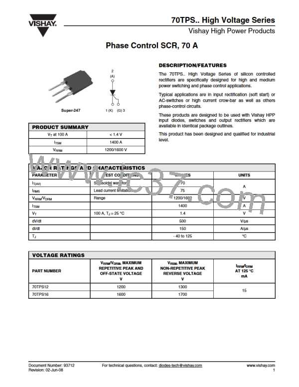
70TPS.. High Voltage Series
Phase Control SCR, 70 A
Vishay High Power Products
THERMAL AND MECHANICAL SPECIFICATIONS
PARAMETER
SYMBOL
TEST CONDITIONS
VALUES
- 40 to 125
- 40 to 150
UNITS
Maximum junction temperature range
Maximum storage temperature range
TJ
°C
TStg
Maximum thermal resistance,
junction to case
RthJC
RthJA
RthCS
DC operation
0.27
40
Maximum thermal resistance,
junction to ambient
°C/W
Typical thermal resistance,
case to heatsink
Mounting surface, smooth and greased
0.2
6
g
Approximate weight
0.21
oz.
minimum
maximum
6 (5)
12 (10)
kgf · cm
(lbf · in)
Mounting torque
Marking device
70TPS12
Case style Super-247
70TPS16
ΔRthJ-hs CONDUCTION PER JUNCTION
SINE HALF WAVE CONDUCTION
RECTANGULAR WAVE CONDUCTION
DEVICE
UNITS
180°
120°
90°
60°
30°
180°
120°
90°
60°
30°
70TPS
Note
• The table above shows the increment of thermal resistance RthJ-hs when devices operate at different conduction angles than DC
0.078
0.092
0.117
0.172
0.302
0.053
0.092
0.125
0.180
0.306
°C/W
Document Number: 93712
Revision: 02-Jun-08
For technical questions, contact: diodes-tech@vishay.com
www.vishay.com
3

 VISHAY [ VISHAY ]