10-PZ124PA032ME03-L629F98Y
datasheet
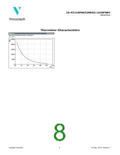
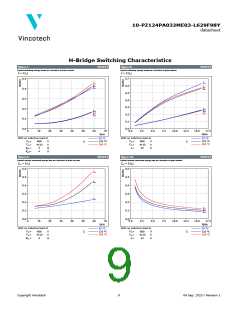
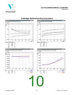
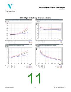
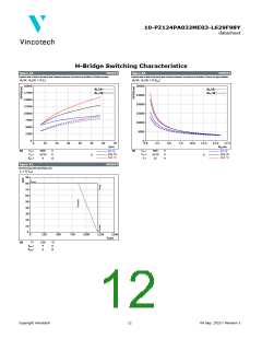
H-Bridge Switching Characteristics
figure 19.
MOSFET
figure 20.
MOSFET
Typical rate of fall of forward and reverse recovery current as a function of drain current
Typical rate of fall of forward and reverse recovery current as a function of turn on gate resistor
diF/dt, dirr/dt = f(ID)
diF/dt, dirr/dt = f(Rgon)
20000
30000
25000
20000
15000
10000
5000
0
diF/dt ‒ ‒ ‒ ‒ ‒
diF/dt ‒ ‒ ‒ ‒ ‒
dirr/dt ──────
17500
15000
12500
10000
7500
5000
2500
0
dirr/dt ──────
0
10
20
30
40
50
60
70
0,0
2,5
5,0
7,5
10,0
12,5
15,0
17,5
ID(A)
Rgon(Ω)
VDS
VGS
=
=
=
VDS
VGS
ID
=
=
=
At
600
V
V
Ω
At
600
V
V
A
25 °C
25 °C
-4/15
4
125 °C
150 °C
-4/15
32
125 °C
150 °C
Tj:
Tj:
Rgon
figure 21.
MOSFET
Reverse bias safe operating area
ID = f(VDS
)
90
ID MAX
80
70
60
50
40
30
20
10
0
0
250
500
750
1000
1250
1500
V
DS(V)
Tj =
At
150
°C
Ω
Rgon
Rgoff
=
=
4
4
Ω
Copyright Vincotech
12
04 Sep. 2020 / Revision 1

 VINCOTECH [ VINCOTECH ]