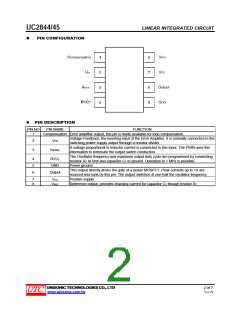
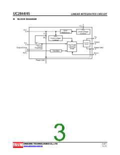
UC2844/45
LINEAR INTEGRATED CIRCUIT
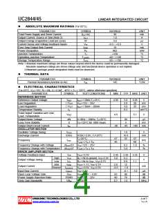
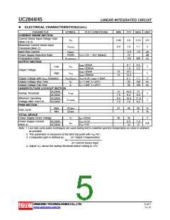
ELECTRICAL CHARACTERISTICS(Cont.)
PARAMETER
SYMBOL
TEST CONDITIONS
MIN
TYP
MAX UNIT
CURRENT SENSE SECTION
Current Sense Input Voltage Gain
(Note 2 & 3)
GV
2.85
0.9
3.0
1.0
3.15
V/V
V
Maximum Current Sense Input
Threshold (Note 2)
VI(THR)
1.1
-10
Input Bias Current
II(BIAS)
PSRR
-2.0
70
μA
dB
ns
Power Supply Rejection Ratio
Propagation Delay
VCC=12V ~ 25V (Note4)
ISINK=20mA
tPLH(IN/OUT)
150
300
OUTPUT SECTION
0.1
1.6
13.5
13.4
0.1
50
0.4
2.2
Low
High
VOL
VOH
V
V
I
SINK=200mA
ISINK=20mA
SINK=200mA
Output Voltage
13
12
I
Output Voltage with UVLO Activated
Output Voltage Rise Time
VOL(UVLO
)
VCC=6.0V, ISINK=1.0mA
CL=1.0nF,TJ=25°C
CL=1.0nF,TJ=25°C
1.1
150
150
V
tR
tF
ns
ns
Output Voltage Fall Time
50
UNDERVOLTAGE LOCKOUT SECTION
UC2844
Startup Threshold
15
7.8
9.0
7.0
16.0
8.4
17
9.0
VTHR
V
V
UC2845
Minimum Operating
Voltage After Turn-On
PWM SECTION
UC2844
UC2845
10.0
7.6
11.0
8.2
VCC(MIN)
Max
Min
DCMAX
47
30
48
50
0
%
%
Duty Cycle
DCMIN
TOTAL DEVICE
Power Supply Zener Voltage
VZ
ICC=25mA
VCC=6.5V
VCC=14V
36
0.5
12
-
V
UC2845
UC2844
1.0
17
Power Supply Current
(Note 4)
ICC
mA
Note: 1. Low duty cycle pulse techniques are used during test to maintain junction temperature as close to ambient
as possible.
2. This parameter is measured at the latch trip point with VFB=0V.
3. Comparator gain is defined as:
ΔV Output Compensation
AV=
ΔV Current Sense Input
4. Adjust VCC above the startup threshold before setting to 15V.
UNISONIC TECHNOLOGIES CO., LTD
5 of 7
Ver.A
www.unisonic.com.tw

 UTC [ Unisonic Technologies ]