Application Information (continues)
Adjustable Regulator Design
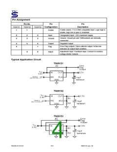
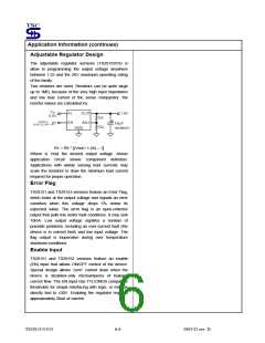
The adjustable regulator versions (TS29152/53) is
allow to programming the output voltage anywhere
between 1.25 and the 26V maximum operating rating
of the family.
Two resistors are used. Resistors can be quite large
up to 1MΩ, because of the very high input impedance
and low bias current of the sense comparator, the
resistor values are calculated by:
R1 = R2 * [(Vout / 1.24) – 1]
Where is Vout the desired output voltage. Above
application circuit shows component definition.
Applications with widely varying load currents may
scale the resistors to draw the minimum load current
required for proper operation.
Error Flag
TS29151 and TS29153 versions feature an Error Flag,
which looks at the output voltage and signals an error
condition when this voltage drops 5% below its
expected value. The error flag is an open-collector
output that pulls low under fault conditions. It may sink
10mA. Low output voltage signifies a number of
possible problems, including an over-current fault (the
device is in current limit) and low input voltage. The
flag output is inoperative during over temperature
shutdown conditions.
Enable Input
TS29151 and TS29152 versions feature an enable
(EN) input that allows ON/OFF control of the device.
Special design allows “zero” current drain when the
device is disabled–only microamperes of leakage
current flow. The EN input has TTL/CMOS compatible
thresholds for simple interfacing with logic, or may be
directly tied to ≤30V. Enabling the regulator requires
approximately 20uA of current.
TS29151/52/53
6-6
2003/12 rev. D

 TSC [ TAIWAN SEMICONDUCTOR COMPANY, LTD ]