TMC5160 DATASHEET (Rev. 1.08 / 2018-NOV-19)
102
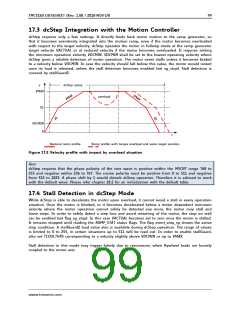
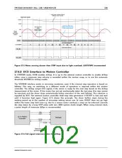
Light motor overload reduces
effective motor velocity
Actual motor velocity
VTARGET
VDCMIN
Steps from STEP input
skipped by the driver due
to light motor overload
0
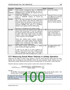
Theoretical sine
wave
corresponding to
fullstep pattern
+IMAX
Phase
Current
(one phase
shown)
0
-IMAX
STEP
LOSTSTEPS would count down if
motion direction is negative
LOSTSTEPS
0
2
4
8
12
16
20
22
24
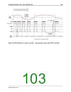
dcStep enabled continuosly
DC_EN
DC_OUT
DCO signals that the driver is not ready for new steps. In this case, the controller does not react to this information.
Figure 17.3 Motor moving slower than STEP input due to light overload. LOSTSTEPS incremented
17.6.2 DCO Interface to Motion Controller
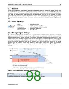
In STEP/DIR mode, DCEN enables dcStep. It is up to the external motion controller to enable dcStep
either, once a minimum step velocity is exceeded within the motion ramp, or to use the automatic
threshold VDCMIN for dcStep enable.
The STEP/DIR interface works in microstep resolution, even if the internal step execution is based on
fullstep. This way, no switching to a different mode of operation is required within the motion
controller. The dcStep output DCO signals if the motor is ready for the next step based on the dcStep
measurement of the motor. If the motor has not yet mechanically taken the last step, this step cannot
be executed, and the driver stops automatically before execution of the next fullstep. This situation is
signaled by DCO. The external motion controller shall stop step generation if DCOUT is low and wait
until it becomes high again. Figure 17.5 shows this principle. The driver buffers steps during the
waiting period up to the number of microstep setting minus one. In case, DCOUT does not go high
within the lower step limit time e.g. due to a severe motor overload, a step can be enforced: override
the stop status by a long STEP pulse with min. 1024 system clocks length. When using internal clock,
a pulse length of minimum 125µs is recommended.
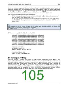
DIR
STEP
µC or Motion
TMC5160
Controller
DCEN
DCO
DCIN
Optional axis
synchronization
Figure 17.4 Full signal interconnection for dcStep
www.trinamic.com

 TRINAMIC [ TRINAMIC MOTION CONTROL GMBH & CO. KG. ]