TMC5130A DATASHEET (Rev. 1.14 / 2017-MAY-15)
89
17.3 microPlyer Step Interpolator and Stand Still Detection
For each active edge on STEP, microPlyer produces microsteps at 256x resolution, as shown in Figure
17.2. It interpolates the time in between of two step impulses at the step input based on the last
step interval. This way, from 2 microsteps (128 microstep to 256 microstep interpolation) up to 256
microsteps (full step input to 256 microsteps) are driven for a single step pulse.
Enable microPlyer by setting the intpol bit in the CHOPCONF register. Operation is only recommended
in STEP/DIR mode.
The step rate for the interpolated 2 to 256 microsteps is determined by measuring the time interval of
the previous step period and dividing it into up to 256 equal parts. The maximum time between two
microsteps corresponds to 220 (roughly one million system clock cycles), for an even distribution of
256 microsteps. At 16MHz system clock frequency, this results in a minimum step input frequency of
16Hz for microPlyer operation. A lower step rate causes the STST bit to be set, which indicates a
standstill event. At that frequency, microsteps occur at a rate of (system clock frequency)/216 ~ 256Hz.
When a stand still is detected, the driver automatically switches the motor to holding current IHOLD.
Attention
microPlyer only works perfectly with a stable STEP frequency. Do not use the dedge option if the STEP
signal does not have a 50% duty cycle.
STEP
Interpolated
0
1
2
3
4
5
6
7
8
9
10
11
12
13
14
15
16
17
18
19
20
21
22
23
32 33 34 35 36 37 38 39 40 41 42 43 44 45 46 47 48 49 50 51 52 53 54 55 56 57 58 59 60 61 62 63 64 65 66
microstep
Motor
angle
2^20 tCLK
STANDSTILL
(stst) active
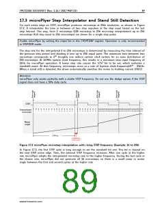
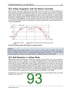
Figure 17.2 microPlyer microstep interpolation with rising STEP frequency (Example: 16 to 256)
In Figure 17.2, the first STEP cycle is long enough to set the standstill bit stst. This bit is cleared on
the next STEP active edge. Then, the external STEP frequency increases. After one cycle at the higher
rate microPlyer adapts the interpolated microstep rate to the higher frequency. During the last cycle at
the slower rate, microPlyer did not generate all 16 microsteps, so there is a small jump in motor
angle between the first and second cycles at the higher rate.
www.trinamic.com

 TRINAMIC [ TRINAMIC MOTION CONTROL GMBH & CO. KG. ]