TMC5130A DATASHEET (Rev. 1.14 / 2017-MAY-15)
54
푉푀
퐼퐿ꢆ푤푒ꢇ 퐿ꢈ푚ꢈ푡 = ꢉ퐵퐿퐴푁퐾 ∗ 푓
∗
ꢊ푊푀
푅ꢋ푂ꢌ퐿
With VM the motor supply voltage and RCOIL the motor coil resistance.
ILower Limit can be treated as a thumb value for the minimum possible motor current setting.
EXAMPLE:
A motor has a coil resistance of 5Ω, the supply voltage is 24V. With TBL=%01 and PWM_FREQ=%00,
tBLANK is 24 clock cycles, fPWM is 2/(1024 clock cycles):
ꢀ
ꢀ4푉
ꢀ4 ꢀ4푉
∗ = ꢀꢀ5ꢍꢎ
퐼퐿ꢆ푤푒ꢇ 퐿ꢈ푚ꢈ푡 = ꢀ4 ꢉꢋ퐿퐾
∗
∗
=
ꢃꢄꢀ4 ꢉꢋ퐿퐾 5Ω
5ꢃꢀ 5Ω
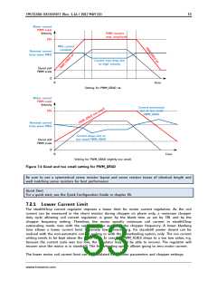
This means, the motor target current must be 225mA or more, taking into account all relevant
settings. This lower current limit also applies for modification of the motor current via the analog
input VREF.
For pwm_autoscale mode, a lower coil current limit applies. This limit can be calculated or measured
using a current probe. Keep the motor run-current setting IRUN well above this lower current limit.
7.2.2 Acceleration
In automatic current regulation mode (pwm_autoscale = 1), the PWM_GRAD setting should be
optimized for the fastest required acceleration ramp. Use a current probe and check the motor current
during (quick) acceleration. A setting of 1 may result in a too slow regulation, while a setting of 15
responds quickly to velocity changes, but might produce regulation instabilities in some
constellations. A setting of 4 is a good starting value.
Hint
Operate the motor within your application when exploring stealthChop. Motor performance often is
better with a mechanical load, because it prevents the motor from stalling due mechanical oscillations
which can occur without load.
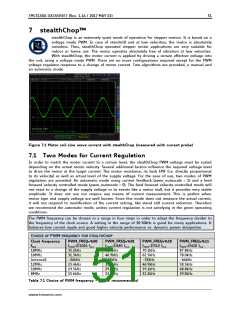
7.3 Velocity Based Scaling
Velocity based scaling scales the stealthChop amplitude based on the time between each two steps,
i.e. based on TSTEP, measured in clock cycles. This concept basically does not require a current
measurement, because no regulation loop is necessary. The idea is a linear approximation of the
voltage required to drive the target current into the motor. The stepper motor has a certain coil
resistance and thus needs a certain voltage amplitude to yield a target current based on the basic
formula I=U/R. With R being the coil resistance, U the supply voltage scaled by the PWM value, the
current I results. The initial value for PWM_AMPL can be calculated:
374 ∗ 푅ꢋ푂ꢌ퐿 ∗ 퐼ꢋ푂ꢌ퐿
푃ꢏꢐ_ꢎꢐ푃ꢑ =
푉푀
With VM the motor supply voltage and ICOIL the target RMS current
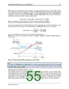
The effective PWM voltage UPWM (1/SQRT(2) x peak value) results considering the 8 bit resolution and
248 sine wave peak for the actual PWM amplitude shown as PWM_SCALE:
푃ꢏꢐ_푆퐶ꢎꢑ퐸 ꢀ4ꢁ
ꢃ
푃ꢏꢐ_푆퐶ꢎꢑ퐸
374
푈ꢊ푊푀 = 푉푀 ∗
∗
∗
= 푉푀 ∗
ꢀ56
ꢀ56
√
ꢀ
www.trinamic.com

 TRINAMIC [ TRINAMIC MOTION CONTROL GMBH & CO. KG. ]