TMC5130A DATASHEET (Rev. 1.14 / 2017-MAY-15)
28
TMC5130A
TMC5130A
#2
TMC5130A
#3
NAI
NAI
NAI
#1
NAO
NAO
RFILT
RFILT
CFILT
CFILT
+VIO
1k
A
B
Master CPU
(µC with RS485
tranceiver)
RTERM
RTERM
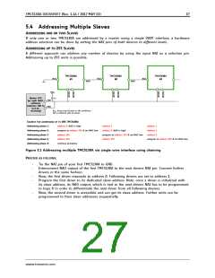
EXAMPLE FOR ADDRESSING UP TO 255 TMC5130A
Addressing phase 1:
Addressing phase 2:
Addressing phase 3:
Addressing phase 4:
Addressing phase X:
address 0, NAO high
address 1
address 0, NAO high
address 1
program to address 254 & set NAO low
address 254
address 1
program to address 253 & set NAO low
address 253
address 0, NAO high
address 254
program to address 252 & set NAO low
continue procedure
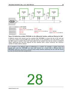
Figure 5.2 Addressing multiple TMC5130A via the differential interface, additional filtering for NAI
A different scheme (not shown) uses bus switches (like 74HC4066) to connect the bus to the next unit
in the chain without using the NAI input. The bus switch can be controlled in the same fashion, using
the NAO output to enable it (low level shall enable the bus switch). Once the bus switch is enabled it
allows addressing the next bus segment. As bus switches add a certain resistance, the maximum
number of nodes will be reduced.
It is possible to mix different styles of addressing in a system. For example, a system using two
boards with each two TMC5130A can have both devices on a board with a different level on
NEXTADDR, while the next board is chained using analog switches separating the bus until the drivers
on the first board have been programmed.
www.trinamic.com

 TRINAMIC [ TRINAMIC MOTION CONTROL GMBH & CO. KG. ]