TMC5130A DATASHEET (Rev. 1.14 / 2017-MAY-15)
120
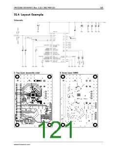
31 Layout Considerations
31.1 Exposed Die Pad
The TMC5130A uses its die attach pad to dissipate heat from the drivers and the linear regulator to
the board. For best electrical and thermal performance, use a reasonable amount of solid, thermally
conducting vias between the die attach pad and the ground plane. The printed circuit board should
have a solid ground plane spreading heat into the board and providing for a stable GND reference.
31.2 Wiring GND
All signals of the TMC5130A are referenced to their respective GND. Directly connect all GND pins
under the device to a common ground area (GND, GNDP, GNDA and die attach pad). The GND plane
right below the die attach pad should be treated as a virtual star point. For thermal reasons, the PCB
top layer shall be connected to a large PCB GND plane spreading heat within the PCB.
Attention
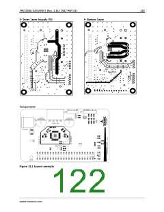
Especially the sense resistors are susceptible to GND differences and GND ripple voltage, as the
microstep current steps make up for voltages down to 0.5mV. No current other than the sense
resistor current should flow on their connections to GND and to the TMC5130A. Optimally place them
close to the IC, with one or more vias to the GND plane for each sense resistor. The two sense
resistors for one coil should not share a common ground connection trace or vias, as also PCB traces
have a certain resistance.
31.3 Supply Filtering
The 5VOUT output voltage ceramic filtering capacitor (4.7µF recommended) should be placed as close
as possible to the 5VOUT pin, with its GND return going directly to the GNDA pin. This ground
connection shall not be shared with other loads or additional vias to the GND plan. Use as short and
as thick connections as possible. For best microstepping performance and lowest chopper noise an
additional filtering capacitor should be used for the VCC pin to GND, to avoid charge pump and digital
part ripple influencing motor current regulation. Therefore place a ceramic filtering capacitor (470nF
recommended) as close as possible (1-2mm distance) to the VCC pin with GND return going to the
ground plane. VCC can be coupled to 5VOUT using a 2.2Ω or 3.3Ω resistor in order to supply the
digital logic from 5VOUT while keeping ripple away from this pin.
A 100nF filtering capacitor should be placed as close as possible to the VSA pin to ground plane. The
motor supply pins VS should be decoupled with an electrolytic capacitor (47μF or larger is
recommended) and a ceramic capacitor, placed close to the device.
Take into account that the switching motor coil outputs have a high dV/dt. Thus capacitive stray into
high resistive signals can occur, if the motor traces are near other traces over longer distances.
www.trinamic.com

 TRINAMIC [ TRINAMIC MOTION CONTROL GMBH & CO. KG. ]